148
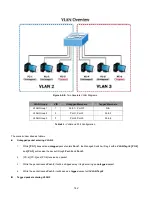
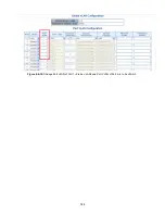
Figure 4-6-15:
VLAN Overlap Port Setting &
VLAN 1 – The Public Area Member Assign
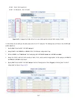
That is, although the VLAN 2 members: Port-1 to Port-3 and VLAN 3 members: Port-4 to Port-6 also belongs to VLAN 1. But with
different PVID settings, packets form VLAN 2 or VLAN 3 is not able to access to the other VLAN.
6. Repeat Steps 1 to 6, set up the VLAN Trunk port at the partner switch and add more VLANs to join the VLAN trunk, repeat
Steps 1 to 3 to assign the Trunk port to the VLANs.
4.6.10.3 Port Isolate
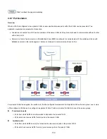
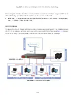
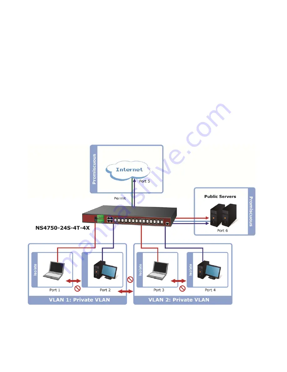
The diagram shows how the Managed Switch handles isolate and promiscuous ports, and the each PC is not able to access each
other PCs of each isolate port. But they all need to access with the same server/AP/Printer. The screen in
Figure 4-6-16
appears.
This section will show you how to configure the port for the server – that could be accessed by each isolate port.
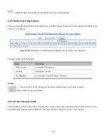
Figure 4-6-16:
The Port Isolate VLAN Diagram
Summary of Contents for NS4750-24S-4T-4X
Page 1: ...NS4750 24S 4T 4X User Manual P N 1702826 REV 00 01 ISS 14JUL14 ...
Page 56: ...56 Figure 4 2 7 Privilege Levels Configuration Page Screenshot ...
Page 110: ...110 Figure 4 4 6 Mirror Configuration Page Screenshot ...
Page 117: ...117 Figure 4 5 4 LACP Port Configuration Page Screenshot ...
Page 174: ...174 Figure 4 7 10 MST1 MSTI Port Configuration Page Screenshot ...
Page 180: ...180 Figure 4 8 2 Multicast Flooding ...
Page 249: ...249 Figure 4 9 18 Voice VLAN Configuration Page Screenshot ...
Page 271: ...271 Counter Counts the number of frames that match this ACE ...
Page 281: ...281 Figure 4 11 4 Network Access Server Configuration Page Screenshot ...
Page 315: ...315 ...
Page 328: ...328 ...
Page 335: ...335 ...
Page 346: ...346 Figure 4 14 1 LLDP Configuration Page Screenshot ...
Page 350: ...350 Figure 4 14 2 LLDP MED Configuration Page Screenshot ...
Page 372: ...372 Figure 4 16 1 Loop Protection Configuration Page Screenshot ...


