158
On the switch level, STP calculates the Bridge Identifier for each switch and then sets the Root
Bridge and the Designated Bridges.
On the port level, STP sets the Root Port and the Designated Ports.
The following are the user-configurable STP parameters for the switch level:
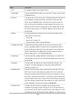
Parameter
Description
Default Value
Bridge Identifier(Not user
configurable
except by setting priority
below)
A combination of the User-set priority and
the switch’s MAC address.
The Bridge Identifier consists of two parts:
a 16-bit priority and a 48-bit Ethernet MAC
address 32768 + MAC
32768 + MAC
Priority
A relative priority for each switch – lower
numbers give a higher priority and a greater
chance of a given switch being elected as
the root bridge
32768
Hello Time
The length of time between broadcasts of
the hello message by the switch
2 seconds
Maximum Age Timer
Measures the age of a received BPDU for a
port and ensures that the BPDU is discarded
when its age exceeds the value of the
maximum age timer.
20 seconds
Forward Delay Timer
The amount time spent by a port in the
learning and listening states waiting for a
BPDU that may return the port to the
blocking state.
15 seconds
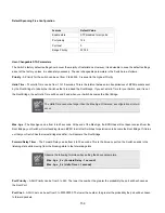
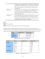
The following are the user-configurable STP parameters for the port or port group level:
Variable
Description
Default Value
Port Priority
A relative priority for each
port –lower numbers give a higher priority
and a greater chance of a given port being
elected as the root port
128
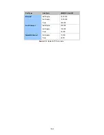
Port Cost
A value used by STP to evaluate paths –
STP calculates path costs and selects the
path with the minimum cost as the active
path
200,000-100Mbps Fast Ethernet ports
20,000-1000Mbps Gigabit Ethernet
ports
0 - Auto
Summary of Contents for NS4750-24S-4T-4X
Page 1: ...NS4750 24S 4T 4X User Manual P N 1702826 REV 00 01 ISS 14JUL14 ...
Page 56: ...56 Figure 4 2 7 Privilege Levels Configuration Page Screenshot ...
Page 110: ...110 Figure 4 4 6 Mirror Configuration Page Screenshot ...
Page 117: ...117 Figure 4 5 4 LACP Port Configuration Page Screenshot ...
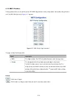
Page 174: ...174 Figure 4 7 10 MST1 MSTI Port Configuration Page Screenshot ...
Page 180: ...180 Figure 4 8 2 Multicast Flooding ...
Page 249: ...249 Figure 4 9 18 Voice VLAN Configuration Page Screenshot ...
Page 271: ...271 Counter Counts the number of frames that match this ACE ...
Page 281: ...281 Figure 4 11 4 Network Access Server Configuration Page Screenshot ...
Page 315: ...315 ...
Page 328: ...328 ...
Page 335: ...335 ...
Page 346: ...346 Figure 4 14 1 LLDP Configuration Page Screenshot ...
Page 350: ...350 Figure 4 14 2 LLDP MED Configuration Page Screenshot ...
Page 372: ...372 Figure 4 16 1 Loop Protection Configuration Page Screenshot ...

