245
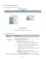
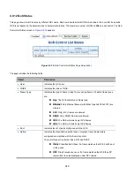
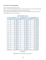
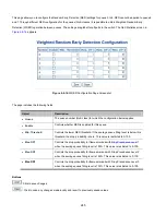
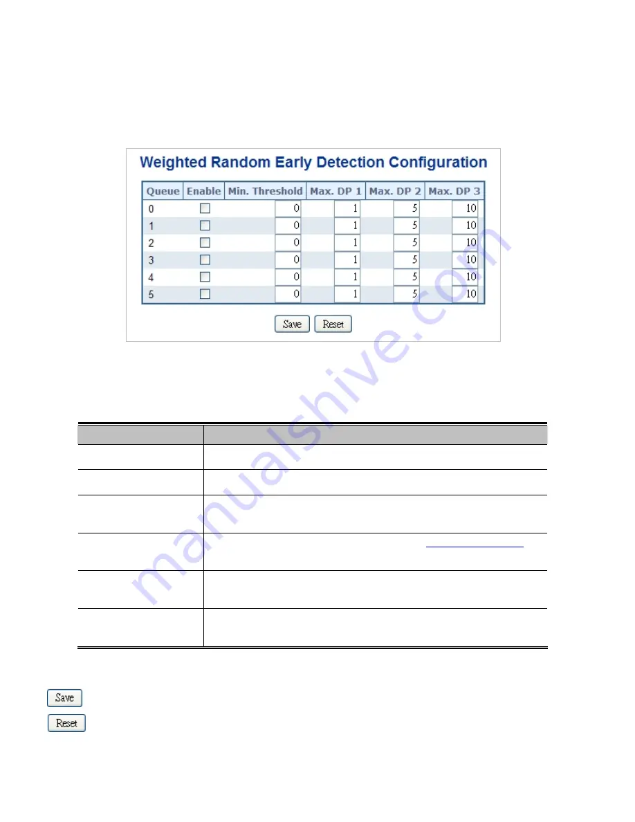
This page allows you to configure the Random Early Detection (RED) settings for queue 0 to 5. RED cannot be applied to queue 6
and 7. Through different RED configuration for the queues (QoS classes) it is possible to obtain Weighted Random Early
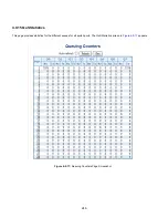
Detection (WRED) operation between queues. The settings are global for all ports in the switch. The QoS Statistics screen in
Figure 4-9-16
appears.
Figure 4-9-16:
WRED Configuration Page Screenshot
The page includes the following fields:
Object
Description
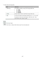
Queue
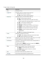
The queue number (QoS class) for which the configuration below applies.
Enable
Controls whether RED is enabled for this queue.
Min. Threshold
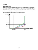
Controls the lower RED threshold. If the average queue filling level is below this
threshold, the drop probability is zero. This value is restricted to 0-100.
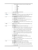
Max. DP1
Controls the drop probability for frames marked with
Drop Precedence Level
1
when the average queue filling level is 100%. This value is restricted to 0-100.
Max. DP2
Controls the drop probability for frames marked with Drop Precedence Level 2
when the average queue filling level is 100%. This value is restricted to 0-100.
Max. DP3
Controls the drop probability for frames marked with Drop Precedence Level 3
when the average queue filling level is 100%. This value is restricted to 0-100.
Buttons
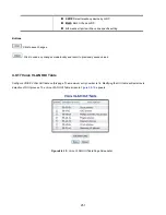
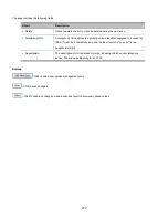
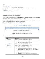
: Click to save changes.
: Click to undo any changes made locally and revert to previously saved values.
Summary of Contents for NS4750-24S-4T-4X
Page 1: ...NS4750 24S 4T 4X User Manual P N 1702826 REV 00 01 ISS 14JUL14 ...
Page 56: ...56 Figure 4 2 7 Privilege Levels Configuration Page Screenshot ...
Page 110: ...110 Figure 4 4 6 Mirror Configuration Page Screenshot ...
Page 117: ...117 Figure 4 5 4 LACP Port Configuration Page Screenshot ...
Page 174: ...174 Figure 4 7 10 MST1 MSTI Port Configuration Page Screenshot ...
Page 180: ...180 Figure 4 8 2 Multicast Flooding ...
Page 249: ...249 Figure 4 9 18 Voice VLAN Configuration Page Screenshot ...
Page 271: ...271 Counter Counts the number of frames that match this ACE ...
Page 281: ...281 Figure 4 11 4 Network Access Server Configuration Page Screenshot ...
Page 315: ...315 ...
Page 328: ...328 ...
Page 335: ...335 ...
Page 346: ...346 Figure 4 14 1 LLDP Configuration Page Screenshot ...
Page 350: ...350 Figure 4 14 2 LLDP MED Configuration Page Screenshot ...
Page 372: ...372 Figure 4 16 1 Loop Protection Configuration Page Screenshot ...


