25
10Base-SR/LR SFP+ interfaces for port25 to port28
LED
Color
Function
Lights
Indicates the link through that SFP port is successfully established with
10Gbps
Green
Off
Indicates that the SFP port is link down
Lights
Indicates the link through that SFP port is successfully established with
1Gbps
LNK/ACT
Orange
Off
Indicates that the SFP port is link down
2.1.3 Wiring the AC Power Input
The rear panel of the NS4750 indicates an AC inlet power socket, which accepts input power from 100 to 240V AC, 50/60Hz.
2.1.4 Wiring the DC Power Input
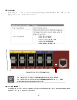
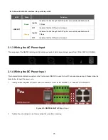
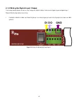
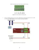
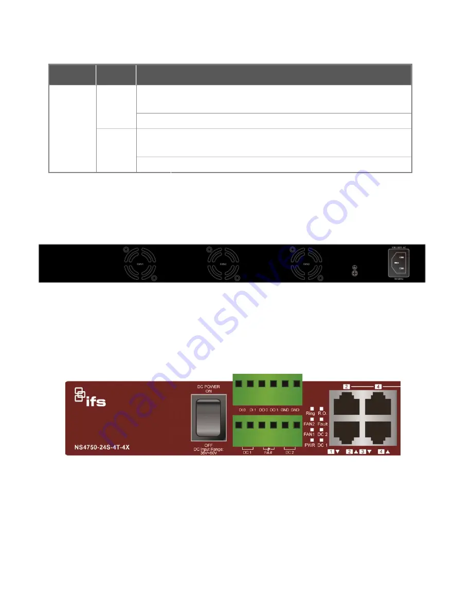
The 6-contact terminal block connector on the front panel of NS4750 is used for two DC redundant power input. Please follow the
steps below to insert the power wire.
1.
Insert positive / negative DC power wires into contacts 1 and 2 for DC POWER 1, or 5 and 6 for DC POWER 2.
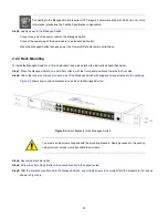
Figure 2-3: NS4750-24S-4T-4X
Upper Panel
2.
Tighten the wire-clamp screws for preventing the wires from loosening.
Summary of Contents for NS4750-24S-4T-4X
Page 1: ...NS4750 24S 4T 4X User Manual P N 1702826 REV 00 01 ISS 14JUL14 ...
Page 56: ...56 Figure 4 2 7 Privilege Levels Configuration Page Screenshot ...
Page 110: ...110 Figure 4 4 6 Mirror Configuration Page Screenshot ...
Page 117: ...117 Figure 4 5 4 LACP Port Configuration Page Screenshot ...
Page 174: ...174 Figure 4 7 10 MST1 MSTI Port Configuration Page Screenshot ...
Page 180: ...180 Figure 4 8 2 Multicast Flooding ...
Page 249: ...249 Figure 4 9 18 Voice VLAN Configuration Page Screenshot ...
Page 271: ...271 Counter Counts the number of frames that match this ACE ...
Page 281: ...281 Figure 4 11 4 Network Access Server Configuration Page Screenshot ...
Page 315: ...315 ...
Page 328: ...328 ...
Page 335: ...335 ...
Page 346: ...346 Figure 4 14 1 LLDP Configuration Page Screenshot ...
Page 350: ...350 Figure 4 14 2 LLDP MED Configuration Page Screenshot ...
Page 372: ...372 Figure 4 16 1 Loop Protection Configuration Page Screenshot ...

