276
Device Roles
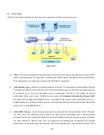
With 802.1X port-based authentication, the devices in the network have specific roles as shown below.
Figure 4-11-1
Client
—the device (workstation) that requests access to the LAN and switch services and responds to requests from the
switch. The workstation must be running 802.1X-compliant client software such as that offered in the Microsoft Windows
XP operating system. (The client is the
supplicant
in the IEEE 802.1X specification.)
Authentication server
—performs the actual authentication of the client. The authentication server validates the identity
of the client and notifies the switch whether or not the client is authorized to access the LAN and switch services. Because
the switch acts as the proxy, the authentication service is transparent to the client. In this release, the Remote
Authentication Dial-In User Service (RADIUS) security system with
Extensible Authentication Protocol (EAP)
extensions is the only supported authentication server; it is available in Cisco Secure Access Control Server version 3.0.
RADIUS operates in a client/server model in which secure authentication information is exchanged between the RADIUS
server and one or more RADIUS clients.
Switch (802.1X device)
—controls the physical access to the network based on the authentication status of the client.
The switch acts as an intermediary (proxy) between the client and the authentication server, requesting identity
information from the client, verifying that information with the authentication server, and relaying a response to the client.
The switch includes the RADIUS client, which is responsible for encapsulating and decapsulating the Extensible
Authentication Protocol (EAP) frames and interacting with the authentication server. When the switch receives EAPOL
Summary of Contents for NS4750-24S-4T-4X
Page 1: ...NS4750 24S 4T 4X User Manual P N 1702826 REV 00 01 ISS 14JUL14 ...
Page 56: ...56 Figure 4 2 7 Privilege Levels Configuration Page Screenshot ...
Page 110: ...110 Figure 4 4 6 Mirror Configuration Page Screenshot ...
Page 117: ...117 Figure 4 5 4 LACP Port Configuration Page Screenshot ...
Page 174: ...174 Figure 4 7 10 MST1 MSTI Port Configuration Page Screenshot ...
Page 180: ...180 Figure 4 8 2 Multicast Flooding ...
Page 249: ...249 Figure 4 9 18 Voice VLAN Configuration Page Screenshot ...
Page 271: ...271 Counter Counts the number of frames that match this ACE ...
Page 281: ...281 Figure 4 11 4 Network Access Server Configuration Page Screenshot ...
Page 315: ...315 ...
Page 328: ...328 ...
Page 335: ...335 ...
Page 346: ...346 Figure 4 14 1 LLDP Configuration Page Screenshot ...
Page 350: ...350 Figure 4 14 2 LLDP MED Configuration Page Screenshot ...
Page 372: ...372 Figure 4 16 1 Loop Protection Configuration Page Screenshot ...

