404
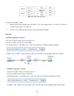
Set ERPS Configuration on Switch 3
Connect PC to switch 3 directly; don’t connect to port 1 & 2
Log-in on the Switch 3 and click “Ring > Ring Wizard”
Set “All Switch Number” = 3 and “Number ID” = 3; click “Next” button to set the ERPS configuration for Switch 3.
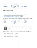
Set “MEP5” = Port2, “MEP6” = Port1 and VLAN ID = 3001; click “Set” button to save the ERPS configuration for Switch 3.
To avoid loop, please don’t connect switch 1, 2 & 3 together in the ring topology before configuring the
end of ERPS .
Follow the configuration or ERPS wizard to connect the Switch 1, 2 & 3 together to establish ERPS application:
MEP2
←→
MEP3 = Switch1 / Port2
←→
Switch2 / Port2
MEP4
←→
MEP5 = Switch2 / Port1
←→
Switch3 / Port2
MEP1
←→
MEP6 = Switch1 / Port1
←→
Switch3 / Port1
Summary of Contents for NS4750-24S-4T-4X
Page 1: ...NS4750 24S 4T 4X User Manual P N 1702826 REV 00 01 ISS 14JUL14 ...
Page 56: ...56 Figure 4 2 7 Privilege Levels Configuration Page Screenshot ...
Page 110: ...110 Figure 4 4 6 Mirror Configuration Page Screenshot ...
Page 117: ...117 Figure 4 5 4 LACP Port Configuration Page Screenshot ...
Page 174: ...174 Figure 4 7 10 MST1 MSTI Port Configuration Page Screenshot ...
Page 180: ...180 Figure 4 8 2 Multicast Flooding ...
Page 249: ...249 Figure 4 9 18 Voice VLAN Configuration Page Screenshot ...
Page 271: ...271 Counter Counts the number of frames that match this ACE ...
Page 281: ...281 Figure 4 11 4 Network Access Server Configuration Page Screenshot ...
Page 315: ...315 ...
Page 328: ...328 ...
Page 335: ...335 ...
Page 346: ...346 Figure 4 14 1 LLDP Configuration Page Screenshot ...
Page 350: ...350 Figure 4 14 2 LLDP MED Configuration Page Screenshot ...
Page 372: ...372 Figure 4 16 1 Loop Protection Configuration Page Screenshot ...


