50
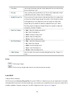
The Current column is used to show the active IP configuration.
Object
Description
Mode
Configure whether the IP stack should act as a
Host
or a
Router
. In
Host
mode, IP traffic between interfaces will not be
routed. In
Router
mode traffic is routed between all interfaces.
DNS Server
This setting controls the DNS name resolution done by the
switch. The following modes are supported:
From any DHCP interfaces
The first DNS server offered from a DHCP lease to a
DHCP-enabled interface will be used.
No DNS server
No DNS server will be used.
Configured
Explicitly provide the IP address of the DNS Server in
dotted decimal notation.
From this DHCP interface
Specify from which DHCP-enabled interface a provided
DNS server should be preferred.
IP Configurations
DNS Proxy
When DNS proxy is enabled, system will relay DNS requests to
the currently configured DNS server, and reply as a DNS
resolver to the client devices on the network.
Delete
Select this option to delete an existing IP interface.
VLAN
The VLAN associated with the IP interface. Only ports in this
VLAN will be able to access the IP interface. This field is only
available for input when creating an new interface.
Enabled
Enable the DHCP client by checking this box.
Fallback
The number of seconds for trying to obtain a DHCP lease.
IPv4
DHCP
Current
Lease
For DHCP interfaces with an active lease, this column show the
current interface address, as provided by the DHCP server.
Address
Provide the IP address of this Managed Switch in dotted decimal
notation.
IPv4
Mask
Length
The IPv4 network mask, in number of bits (
prefix length
). Valid
values are between 0 and 30 bits for a IPv4 address.
IP Address
IPv6 Address
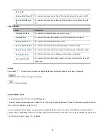
Provide the IP address of this Managed Switch. A IPv6 address
is in 128-bit records represented as eight fields of up to four
hexadecimal digits with a colon separating each field (:).
Summary of Contents for NS4750-24S-4T-4X
Page 1: ...NS4750 24S 4T 4X User Manual P N 1702826 REV 00 01 ISS 14JUL14 ...
Page 56: ...56 Figure 4 2 7 Privilege Levels Configuration Page Screenshot ...
Page 110: ...110 Figure 4 4 6 Mirror Configuration Page Screenshot ...
Page 117: ...117 Figure 4 5 4 LACP Port Configuration Page Screenshot ...
Page 174: ...174 Figure 4 7 10 MST1 MSTI Port Configuration Page Screenshot ...
Page 180: ...180 Figure 4 8 2 Multicast Flooding ...
Page 249: ...249 Figure 4 9 18 Voice VLAN Configuration Page Screenshot ...
Page 271: ...271 Counter Counts the number of frames that match this ACE ...
Page 281: ...281 Figure 4 11 4 Network Access Server Configuration Page Screenshot ...
Page 315: ...315 ...
Page 328: ...328 ...
Page 335: ...335 ...
Page 346: ...346 Figure 4 14 1 LLDP Configuration Page Screenshot ...
Page 350: ...350 Figure 4 14 2 LLDP MED Configuration Page Screenshot ...
Page 372: ...372 Figure 4 16 1 Loop Protection Configuration Page Screenshot ...


