75
4.2.17 Faulty
Alarm
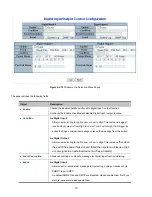
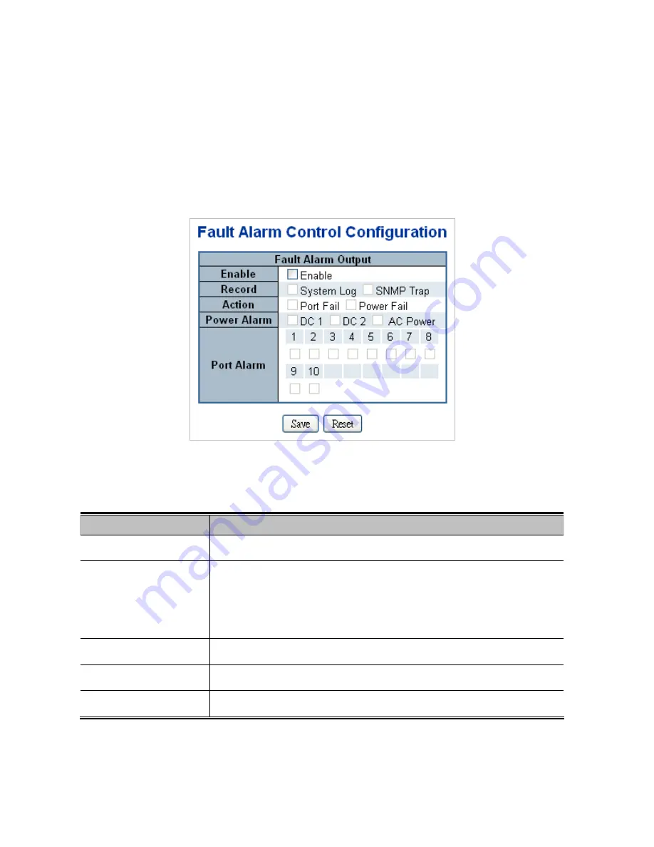
The Faulty Relay Alarm function provides the Power Failure and Port Link Down/Broken detection. With both power input 1 and
power input 2 installed and the check boxes of power 1/power 2 ticked, the FAULTY LED indicator will then be possible to light up
when any one of the power failures occurs. As for the Port Link Down/Broken detection, the FAULT LED indicator will light up
when the port failure occurs; certainly the check box beside the port must be ticked first. Please refer to the segment of ‘
Wiring
the Fault Alarm Contact
’ for the failure detection. The Configuration screen in
Figure 4-2-20
appears.
Figure 4-2-20
Windows File Selection Menu Popup
The page includes the following fields:
Object
Description
Enable
Allows user to enable Fault Alarm function.
Record
Allows user to record alarm message to System log, syslog or issues out via
SNMP Trap or SMTP.
As default SNMP Trap and SMTP are disabled, please enable them first if you
want to issue alarm message via them.
Action
Allows user to monitor and alarm from port fail or power fail.
Power Alarm
Allows user to choose which power module want to be monitored.
Port Alarm
Allows user to choose which port want to be monitored.
Buttons
Summary of Contents for NS4750-24S-4T-4X
Page 1: ...NS4750 24S 4T 4X User Manual P N 1702826 REV 00 01 ISS 14JUL14 ...
Page 56: ...56 Figure 4 2 7 Privilege Levels Configuration Page Screenshot ...
Page 110: ...110 Figure 4 4 6 Mirror Configuration Page Screenshot ...
Page 117: ...117 Figure 4 5 4 LACP Port Configuration Page Screenshot ...
Page 174: ...174 Figure 4 7 10 MST1 MSTI Port Configuration Page Screenshot ...
Page 180: ...180 Figure 4 8 2 Multicast Flooding ...
Page 249: ...249 Figure 4 9 18 Voice VLAN Configuration Page Screenshot ...
Page 271: ...271 Counter Counts the number of frames that match this ACE ...
Page 281: ...281 Figure 4 11 4 Network Access Server Configuration Page Screenshot ...
Page 315: ...315 ...
Page 328: ...328 ...
Page 335: ...335 ...
Page 346: ...346 Figure 4 14 1 LLDP Configuration Page Screenshot ...
Page 350: ...350 Figure 4 14 2 LLDP MED Configuration Page Screenshot ...
Page 372: ...372 Figure 4 16 1 Loop Protection Configuration Page Screenshot ...


