background image

Installation Guide 

7. 

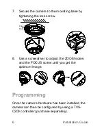
Secure the camera to the mounting base by 

tightening the lock screw. 


8.  Use a screwdriver to adjust the ZOOM screw 

and the 

FOCUS screw until you get the 

optimum image.  


Programming  

Once the camera hardware has been installed, the 

camera can then be configured


by using a TVS

-

C200 controller (purchase separately).  

Clip

Plate

Summary of Contents for TruVision TVT-2202

Page 1: ...TruVision IR Turret Camera TVT 2202 TVT 4202 Installation Guide P N 1072921 REV A ISS 10FEB15 ...

Page 2: ......

Page 3: ...Installation Guide 1 Contents Product overview 2 Camera description 3 Installation 4 Programming 6 Specifications 7 Setup menu 8 Regulatory information 9 ...

Page 4: ...Camera Installation Guide for models TVT 2202 TVT 4202 This guide describes a standard installation Package contents Camera with power and video output cables 4 M4 screws 4 x 25 mm and 4 dry wall anchors Ø7 5 x 24 5 mm for wall or ceiling installation Template Hex wrench ...

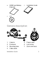
Page 5: ...Installation Guide 3 WEEE and Battery Disposal Installation Guide CD Camera description 1 Camera 2 Enclosure 3 Mounting base 4 Video cable 5 Power cable 6 Lock screw 7 Zoom and focus ...

Page 6: ...g the template place it level against the mounting surface and mark the position of the mounting holes 2 Following all local codes drill and prepare the mounting holes 3 Loosen the lock screw and release the clip plate to release the camera from the mounting base ...

Page 7: ... the cables to the cable hole and connect the corresponding cables Connect a 75 ohm coaxial video cable to the video cable and connect a 12 VDC power supply to the power cable 6 Adjust the camera according to the figure below to get an optimum angle Clip Plate 0 360 0 75 0 360 ...

Page 8: ...tening the lock screw 8 Use a screwdriver to adjust the ZOOM screw and the FOCUS screw until you get the optimum image Programming Once the camera hardware has been installed the camera can then be configured by using a TVS C200 controller purchase separately Clip Plate ...

Page 9: ... menu Please refer to the configuration manual for further information on setting up the camera Program the camera by attaching a standard video monitor to the system Specifications Power supply 12 VDC Current Max 420 mA Power consumption Max 5W Weight net 1 76 lb 800 g Dimensions Ø 5 28 4 88 3 48 in Ø 134 2 123 9 88 1 mm ...

Page 10: ...8 Installation Guide Setup menu ...

Page 11: ...tative UTC Fire Security B V Kelvinstraat 7 6003 DH Weert The Netherlands Certification N4131 FCC compliance Class A Class A This equipment has been tested and found to comply with the limits for a Class A digital device pursuant to part 15 of the FCC Rules These limits are designed to provide reasonable protection against harmful interference when the equipment is operated in a commercial environ...

Page 12: ...Canada European Union directives 12004 108 CE EMC directive Hereby UTC Fire Security declares that this device is in compliance with the essential requirements and other relevant provisions of Directive 2004 108 EC 2012 19 EU WEEE directive Products marked with this symbol cannot be disposed of as unsorted municipal waste in the European Union For proper recycling return this product to your local...

Reviews: