background image

"

NOTICE

The information contained herein is proprietary and is provided solely for the

purpose of allowing customers to operate and service Intermec manufactured

equipment and is not to be released, reproduced, or used for any other purpose

without written permission of Intermec.

We welcome your comments concerning this publication. Although every effort has

been made to keep it free of errors, some may occur. When reporting a specific

problem, please describe it briefly and include the book title and part number, as

well as the paragraph or figure number and the page number.

Send your comments to:

Intermec Technologies Corporation

Publications Department

550 Second Street SE

Cedar Rapids, IA 52401

INTERMEC, NORAND, NOR*WARE, and PEN*KEY are registered trademarks

of Intermec Technologies Corporation.

Ó

1995 Intermec Technologies Corporation. All rights reserved.

This publication printed on recycled paper.

Summary of Contents for 6100 Series

Page 1: ...6100 Series Docks INSTALLATION INSTRUCTIONS PN 962 020 003 Revision E April 2000 ...

Page 2: ...ort has been made to keep it free of errors some may occur When reporting a specific problem please describe it briefly and include the book title and part number as well as the paragraph or figure number and the page number Send your comments to Intermec Technologies Corporation Publications Department 550 Second Street SE Cedar Rapids IA 52401 INTERMEC NORAND NOR WARE and PEN KEY are registered ...

Page 3: ...1 12 Single Dock 9 Pin Male Serial Port 1 13 Single Dock 25 Pin Female Serial Port 1 15 Multidock 9 Pin Female RS 485 Connector 1 17 Vehicle Dock 3 Pin Male Power Connector 1 18 RS 485 LAN Terminator 1 19 SECTION 2 Single and Multidock Installation Installation Guidelines 2 1 Electrical Requirements 2 2 Electrical and Communication Connections 2 3 Dock Installation 2 4 Mounting Structure 2 4 Singl...

Page 4: ...Cable Assembly 3 6 Assembling the In line Fuse Holder 3 6 Terminating Wire Ends 3 7 Connecting the Fuse Holder 3 9 Side Battery Terminal Post Connection 3 10 Top Battery Terminal Post Connection 3 12 Installing Your Vehicle Dock With Other Equipment 3 14 Installing an Optional Printer 3 15 Vehicle Dock and Printer 3 16 Fastening the Ground Cable 3 16 Installing an Optional Keyboard Tray 3 17 Vehic...

Page 5: ... Figure 2 4 Mounting Brackets For Multidock 2 6 Figure 2 5 Positioning the Mounting Clips 2 7 Figure 2 6 Attaching the Dock to the Mounting Brackets 2 8 Figure 3 1 Assembling the In line Fuse Holder 3 7 Figure 3 2 Terminating Wire Ends 3 8 Figure 3 4 Side Battery Terminal Posts 3 11 Figure 3 5 Top Battery Terminal Posts 3 13 Figure 3 6 Stripping the Power Cable Jacket 3 14 Figure 3 7 Wiring Diagra...

Page 6: ... Pin Serial Port Connector Pin Outs 1 16 Table 1 5 Multidock 9 Pin Connector Pin Outs 1 17 Table 3 1 Vehicle Dock Part Number 225 558 001 3 3 Table 3 2 Parts and Accessories for Vehicle Battery Kit 203 344 001 002 3 4 Table 3 3 Cables for Connecting a Vehicle Dock to Vehicle Battery Kit 203 344 001 3 5 Table 3 4 Cables for Connecting a Vehicle Dock and Printer to Vehicle Battery Kit 203 344 002 3 ...

Page 7: ... eight hand held computers Vehicle dock provides a secure place to contain your hand held computer Along with a locking device for your computer the vehicle dock also provides charging and network communications Section 2 covers the installation instructions for the single and multidocks This section includes guidelines and con siderations for mounting shelves and mounting brackets Section 3 cover...

Page 8: ...osensing and switching power supply An ac connector for using the universal power cord The ability for the hand held computer to receive both charging and operating power The capability to connect your hand held computer to a network A latch and key to seat your hand held computer into place allowing for security and good connector contact for charging and data communication The capability to conn...

Page 9: ... 3 Figure 1 1 Single Dock 5 3 1 25 Pin female serial RS 232 RS 485 port connector 2 9 Pin male RS 232 serial port connector 3 AC connector 4 Charging indicator red charging blinking red error condition green fully charged 5 8 Pin interface connector 4 1 2 Front view Back view ...

Page 10: ...tertop or wall Features of the multidock include It holds up to eight hand held computers An autosensing and switching power supply An ac connector for using the universal power cord The ability for the hand held computers to receive both charging and operating power The capability to connect your hand held computers to a network ...

Page 11: ...s Dock Installation Instructions 1 5 Figure 1 2 Multidock 1 2 Front view Back view 3 4 1 Individual hand held computer cups 2 Charging indicators red charging blinking red error condition green fully charged 3 RS 485 connectors 4 AC connector ...

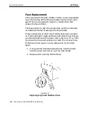
Page 12: ...ltidock are identical Detail drawings are shown below If the indicator s on the front of either dock does not light or if terminals go to sleep and their batteries do not charge you should make sure the power cord is secure If it is then you should remove and examine or test the internal fuse If the fuse is bad open circuit replace and try the dock again 1 Using a small flat blade screwdriver slip...

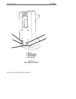
Page 13: ...are a number of installation steps that must be completed when using this type of dock Cables have to be routed from the dock to the vehicle battery The dock must also be securely mounted to ensure that the hand held computer is stored safely and re ceives power Figure 1 4 Vehicle Dock Front View 1 2 1 Spring loaded hand held computer retention bracket 2 Lock 3 Connection and power indicator LED 3...

Page 14: ...ECTION 1 General Information 1 8 6100 Series Dock Installation Instructions Figure 1 5 Vehicle Dock Back View 1 2 2 5 4 3 1 RF jack 2 Com 3 connector 3 External keyboard 4 Com 1 connector 5 DC power jack ...

Page 15: ...nformation 6100 Series Dock Installation Instructions 1 9 Figure 1 6 Vehicle Dock Computer Holder 1 2 3 4 1 Speaker slot 2 Communication Serial port 3 Infrared lens 4 Hand held computer retention pins two one on each side ...

Page 16: ...7 kg Dimensions Length side to side 8 inches 20 32 cm Width front to back Without cables 5 3 4 inches 14 61 cm With cables 8 1 2 inches 21 59 cm Height top to bottom Dock only 5 1 2 inches 13 97 cm Dock with computer and no endcap 10 1 8 inches 25 72 cm Dock with computer and endcap 11 1 4 inches 28 58 cm Min spacing between shelves 17 inches 43 18 cm Figure 1 7 Single Dock With Computer and Cable...

Page 17: ...8 cm Width front to back Without cables 6 inches 15 24 cm With cables 13 1 4 inches 33 66 cm Height top to bottom Dock only 5 3 4 inches 14 61 cm Dock with computer and no endcap 10 1 8 inches 25 72 cm Dock with computer and endcap 11 1 4 inches 28 58 cm Min spacing between shelves 17 inches 43 18 cm Figure 1 8 Multidock With Computer and Cable Connectors ...

Page 18: ... 22 86 cm Width front to back 6 5 inches 15 24 cm Height top to bottom Dock only 7 1 2 inches 19 05 cm Dock with computer 10 1 8 inches 25 72 cm Connector Pin Outs 8 Pin Interface Connector Figure 1 9 Interface Connector 7 5 3 1 8 6 4 2 Table 1 1 8 Pin Connector Pin Outs Pin Signal Name Function on Dock I O from Dock 1 BCLK Battery Interface Clock Input 2 DOCKPWR 12 Volt Charge Power Output ...

Page 19: ...ut Single Dock 9 Pin Male Serial Port Figure 1 10 Single Dock 9 Pin Male Connector The single dock RS 232 port available on a DB9 male connector is gen erated from the IrDA interface on your computer It has no hardware handshake available and has the following signals 1 2 3 4 5 6 7 8 9 Table 1 2 Single Dock 9 Pin Serial Port Connector Pin Outs Pin Signal Name Function Standard Function on PC I O o...

Page 20: ...Set Baud Rate Data Send Ready Input 7 RTS Forced High Request To Send Output 8 CTS To Set Baud Rate Clear To Send Input 9 NC No Connect Ring Indicator Use pin 6 and 8 of this RS 232 connector to set the baud rate of the IrDA controller located inside the single dock The default is to have the baud rate set at 9600 Table 1 3 on page 1 14 shows the baud rate for each combination of control lines Tab...

Page 21: ...you use the Norand cable part number 226 257 001 This cable will ground the 485 enable line and provide two 9 pin connectors to connect to the standard RS 485 cables Norand part number 226 103 xxx xxx indicates length Your sales team will help you determine the length you need for your installation Two connectors are provided so that the RS 485 host and a resistive RS 485 LAN terminator NPN 226 25...

Page 22: ...eady To Send 5 CTS Clear To Send 6 DSR Not Driven Connected to pin 20 DTR 7 GND Ground 8 DCD Data Carrier Detect 9 NC No Connect 10 NC No Connect 11 485 RS 485 Positive Side 12 NC No Connect 13 NC No Connect 14 NC No Connect 15 NC No Connect 16 NC No Connect 17 NC No Connect 18 485 RS 485 Negative Side 19 485 Enable If grounded 485 Enabled 20 DTR Not Driven Connected to pin 6 DSR 21 NC No Connect ...

Page 23: ...Connect 25 NC No Connect Multidock 9 Pin Female RS 485 Connector Figure 1 12 Multidock 9 Pin Female RS 485 Connector 1 2 3 4 5 6 7 8 9 Table 1 5 Multidock 9 Pin Connector Pin Outs Pin Signal Name Function I O to Dock 1 NC No Connect 2 485 485 Positive Data Signal I O 3 485 485 Negative Data Signal I O 4 NC No Connect 5 NC No Connect 6 NC No Connect 7 GND Ground 8 GND Ground 9 NC No Connect ...

Page 24: ...tion 1 18 6100 Series Dock Installation Instructions Vehicle Dock 3 Pin Male Power Connector Figure 1 13 Vehicle Dock 3 Pin Male Power Connector Pin 1 chassis ground green wire Pin 3 ground white wire Pin 2 12 volts black wire ...

Page 25: ...r for this termi nator comes from an external ac wall adapter A terminator is always attached to the LAN port of the last multidock in the series When using 6000 Series hand held computers or a mixture of 4000 and 6000 Series computers always use the ap propriate RS 485 terminator when the total LAN cable length exceeds 100 feet Work with your sales team to de termine your exact requirements ...

Page 26: ...SECTION 1 General Information 1 20 6100 Series Dock Installation Instructions ...

Page 27: ... loading dock or staging area Walk in coolers or other refrigerated storage areas Over heated areas such as incubation rooms High humidity environments Confined unventilated space such as a storage closet Wherever chemical dust fumes or corrosives materi als are present Wall mounting your dock involves a suitable structure to hold the weight of one or several docking units Wall mount ing kits are ...

Page 28: ...of an outlet The outlets must be grounded three prong and with sufficient capacity to carry the load for the number of docks and other electrical devices per circuit breaker If you are uploading and downloading data with the host computer you will need to have data jacks close by You will also need to have communication cables for connecting the docks to the jacks The connectors are identified in ...

Page 29: ...and Communication Connections Figure 2 1 and Figure 2 2 show the connectors for the single and multidocks Figure 2 1 Single Dock Connectors 1 2 1 RS 232 or RS 485 serial port 2 RS 232 serial port 3 AC connector 3 Back view Figure 2 2 Multidock Connectors Back view 1 2 1 RS 485 connectors 2 AC connector ...

Page 30: ...ting brackets first is the preferred method and therefore the instructions for that follow Mounting Structure You can install the docks on most structures made of wood concrete or cinder block Use anchors that will support the weight and are designed for the type of wall you will be us ing Some anchor selection guidelines are for Concrete structures use metal expansion anchors Plastic anchors or d...

Page 31: ...cket Installation 1 Position one mounting bracket at the desired height 2 Use 1 4 inch or larger hardware to secure one mount ing bracket to the wall 3 Install the second mounting bracket level with the first and no more than eight inches from the first bracket Figure 2 3 Mounting Brackets For Single Dock 8 Maximum ...

Page 32: ...lywood 5 8 inch thickness or greater reinforcement 1 Position one mounting bracket at a suitable height and use 1 4 inch or larger hardware lagscrew or con crete fastener to secure one mounting bracket to the wall 2 Use three fasteners in each bracket 3 Install the second bracket level with the first and 24 to 34 inches from it NOTE When installing several multidocks across a wall be sure to allow...

Page 33: ...e edge of the mounting bracket as a guide and make a pencil line on the bottom of each end of the dock going from the front to the back 3 Lay the dock on its side so the bottom of the dock is towards you 4 Tilt the clips and slide into the channels on the dock 5 Press the clips flush against the bottom of the dock 6 Align the edge of each clip with the pencil mark you made earlier 7 Use a short st...

Page 34: ...e center hole at each mounting loca tion and lower the dock onto the brackets NOTE To show the mounting clips and their placement location into the mounting bracket Figure 2 6 shows them not attached to the under side of the dock They would normally be attached before placing the dock on the mounting bracket 10 Install the lock washers and nuts and tighten Tighten these snugly so as not to strip t...

Page 35: ...o store the computer In addition the vehicle electri cal system provides power to recharge the batteries and to operate a printer if one is installed NOTE Intermec Corporation is not responsible for loss or damage to the hand held computers printers or docks resulting from improper installation NOTE Mounting bracket and bracket installation hardware are not provided in this kit but can be purchase...

Page 36: ...rings for con necting the electrical cable directly to the vehicle bat tery The vehicle dock mounting location must not restrict the drivers view Mount the dock and cables away from the brake pedal accelerator steering wheel emergency brake gear shift and any other area that interferes with safe operation of the vehicle A waterproof in line fuse holder must be installed onto the end of the gray ve...

Page 37: ...d connector or it may in volve cutting the connector off and wiring directly to the fuse block Installation Tools Required Wire crimping and stripping tool An electric drill 26 drill bit Common hand tools 3 8 wrench flat blade screwdriver phillips screwdriver allen wrenches and small punch Table 3 1 Vehicle Dock Part Number 225 558 001 Description Part Number Qty Vehicle Dock 225 558 001 1 Screws ...

Page 38: ...condition in the terminal battery and in the printer battery if one is installed in the vehicle Excess electrical noise can be severe enough to defeat the electrical filtering that is built into your equipment Defec tive ignition wiring damaged insulation or a faulty vehicle electrical component can cause electrical noise When this happens computers and other equipment can behave un predictably Ta...

Page 39: ...ions detail how to route the cable install the in line fuse and make the battery connection onto a side terminal post or top terminal post type battery Decide the mounting location for the vehicle dock and the cables When you are certain your arrangement works and that cables will reach from the batteries to the power con verter to the dock proceed with the instructions below 1 Completely install ...

Page 40: ...led in which case you should skip the following fuse holder assembly procedures and go to the next set of instructions Connecting the Fuse Holder on page 3 9 If the fuse holder is not preassembled carefully follow these instructions to assemble the in line fuse holder 1 Locate the in line fuse holder components 2 Cut the red wire in the battery power cable midway between its end and the cable jack...

Page 41: ...r boot together 8 Go to Terminating the Wire Ends Figure 3 1 Assembling the In line Fuse Holder 1 Fuse clips 2 Red wire 6 7 inches 3 Fuse holder boot 4 Red wire 5 Power cable 6 Brown wire 1 2 3 4 6 5 Terminating Wire Ends Crimp 3 8 inch terminal rings to the stripped end of the brown wire and to the red wire from the fuse holder See the battery drawing and instructions for recommended assem bly to...

Page 42: ... Installation 3 8 6100 Series Dock Installation Instructions 2 Crimp the 3 8 terminal ring onto this wire 3 Crimp a 3 8 terminal ring onto the red wire from the end of the in line fuse holder Figure 3 2 Terminating Wire Ends ...

Page 43: ... power cable when your kit in cludes a preassembled fuse holder 1 Strip the brown wire 2 Crimp the 3 8 terminal ring 1 onto the brown wire 3 Locate the fuse link 2 it attaches to the red wire 4 Shorten the red wire if desired 5 Then strip 1 4 of insulation from the red wire 6 Securely crimp the fuse link splice 3 onto the red wire 1 3 8 terminal ring 2 Fuse link assembly 3 Fuse link splice 4 Acces...

Page 44: ...st 9 furnished in kit 3 Slip a 3 8 inch washer 8 onto the battery terminal post 4 Slide the positive red wire fuse link 7 terminal ring from the battery cable onto the positive battery ter minal post 5 Slip a second 3 8 inch washer 8 onto the battery ter minal post 6 Slide the vehicle positive battery cable 3 onto the bat tery terminal post 7 Thread the post assembly steps 2 6 above into the posit...

Page 45: ...lation Instructions 3 11 1 Battery 2 Positive battery post 3 Battery cable positive 4 Fuse link 5 Brown wire negative 6 Power cable 7 Red wire positive 8 Washers 9 Battery terminal post positive 10 Nut 1 2 3 4 5 6 Figure 3 4 Side Battery Terminal Posts 7 8 9 10 ...

Page 46: ...s 2 Replace the posts removed in step 1 with 5 16 x 1 1 2 posts 4 and nut 10 furnished in the installation kit Tighten nut securely 3 Slip a 3 8 inch washer 9 onto the extended end of each battery terminal post 4 Slide the positive red wire fuse link 8 terminal ring from the battery cable onto the positive battery terminal post 4 5 Slip a second 3 8 inch washer 9 onto the battery ter minal post 4 ...

Page 47: ...llation Instructions 3 13 1 Battery 2 Positive battery terminal 3 Battery cable positive 4 5 16 x 1 1 2 post 5 Fuse link 6 Brown wire negative 7 Gray power cable 8 Red wire positive 9 Washers 10 Nut 2 10 1 3 4 5 6 Figure 3 5 Top Battery Terminal Posts 2 7 9 8 ...

Page 48: ... or satellite track ing device in which case you will need to modify the black dock cable part number 206 951 001 to connect into a ve hicle fuse block that the installation team would install If this is the case you could install the cable designed to connect to the fuse block part number 226 109 001 Or you could cut off the white connector from the end of the black dock cable and wire the dock p...

Page 49: ...e dock up to six feet 1 83 m apart This kit includes a power cable with a noise filter and a ground strap The installation for a system that includes a printer refer to pages 3 15 and 3 17 for the wiring diagram for the Y cable and installing the power cable with noise filter Figure 3 7 Wiring Diagram for Installing a Printer Battery Vehicle Dock Printer 1 2 1 Remote data cable 2 Y cable 3 Battery...

Page 50: ...88 001 between the vehicle dock and the printer This cable allows the terminal to communicate with the printer Plug the appropriate end of this cable into the vehicle dock and the other end into the printer Fastening the Ground Cable The power cable connector has a braided wire grounding strap that must be fastened to vehicle sheet metal to ensure proper cable shielding Follow the steps below to f...

Page 51: ...le connects to vehicle battery Installing an Optional Keyboard Tray An optional keyboard tray can be installed to work with your vehicle mount bracket The keyboard tray kit part number 203 542 001 includes Bracket plate p n 653 402 001 Bracket mount p n 653 403 001 Mounting hardware The keyboard tray does not include the keyboard The key board to use with this tray is part number To assemble your ...

Page 52: ...k Installation 3 18 6100 Series Dock Installation Instructions Figure 3 9 Assembling Keyboard Tray 2 Attach the vehicle dock to the tray using the four 3 4 inch machine screws Figure 3 10 Figure 3 10 Attaching Dock to Tray ...

Page 53: ...Dock Installation Instructions 3 19 3 Slide the optional keyboard p n 340 045 001 into the tray and attach the keyboard cable to the hand held computer Figure 3 11 Inserting Keyboard into Tray and Attaching Cable to Computer 3 Keyboard connector 2 1 ...

Page 54: ...ck Kit 203 522 001 Fixed Mount Kit 203 530 001 Adjustable Mount Table 3 5 Vehicle Dock Adjustable Mount Kit Kit 203 530 001 Description Part Number Qty Vehicle Swivel Mount 653 391 001 1 Vehicle Mount Bracket 653 392 001 1 1 4 20 Regular Lock Nuts 802 117 000 4 1 4 Flat Washers 803 102 000 8 10 32 x 3 8 Pan Head Screws 800 402 001 4 14 10 x 1 3 4 Hex Washer Screws 800 359 002 4 ...

Page 55: ...SECTION 3 Vehicle Dock Installation 6100 Series Dock Installation Instructions 3 21 Figure 3 12 Vehicle Dock Adjustable Mount Bracket ...

Page 56: ...SECTION 3 Vehicle Dock Installation 3 22 6100 Series Dock Installation Instructions Figure 3 13 Vehicle Dock Adjustable Mount with Computer Inserted ...

Page 57: ...SECTION 3 Vehicle Dock Installation 6100 Series Dock Installation Instructions 3 23 Figure 3 14 Vehicle Dock Adjustable Mount Back Side ...

Page 58: ...t Kit 203 522 001 Description Part Number Qty Vehicle Dock Mount 653 372 001 1 1 4 20 Regular Lock Nuts 802 117 000 4 1 4 Flat Washers 803 102 000 8 1 4 20 x 1 Hex Head Screws 801 195 002 4 10 32 x 3 8 Pan Head Screws 800 402 001 4 14 10 x 1 3 4 Hex Washer Screws 800 359 002 4 Figure 3 15 Vehicle Dock Fixed Mount Bracket ...

Page 59: ...SECTION 3 Vehicle Dock Installation 6100 Series Dock Installation Instructions 3 25 Figure 3 16 Vehicle Dock Fixed Mount Bracket Back Side ...

Page 60: ...SECTION 3 Vehicle Dock Installation 3 26 6100 Series Dock Installation Instructions Figure 3 17 Vehicle Dock Fixed Mount with Computer Inserted ...

Page 61: ...icle dock by itself connect one end of the dc power cable part number 206 951 001 to the vehicle dock the other end plugs into the previously installed battery cable Figure 3 18 Vehicle Dock Connectors 5 6 2 1 4 3 1 RF jack 2 Com 3 connector 3 External keyboard 4 Com 1 connector 5 Power cable connector nut 6 Notched dc power connector ...

Page 62: ... Installation Instructions Vehicle Dock Keylock Your Vehicle Dock has a keylock option that allows you to insert your hand held computer lock it into the dock and remove the key Figure 3 19 illustrates the use of the key lock Figure 3 19 Vehicle Dock Keylock ...

Page 63: ...f you need to jump start your vehicle from another vehicle battery disconnect the power cable running to the printer or dock Failure to do so can result in loss or damage to your hand held computer To disconnect Unscrew at the printer or dock or Disconnect at the Y connection where the short cable plugs into the long cable ...

Page 64: ...SECTION 3 Vehicle Dock Installation 3 30 6100 Series Dock Installation Instructions ...

Page 65: ...use installation 3 6 Installation cables 3 5 in line fuse 3 6 terminating the wire ends 3 7 side battery terminal post cable connection 3 10 top battery terminal post cable connection 3 12 Installation guidelines multidock 2 1 single dock 2 1 vehicle dock 3 2 Installation kits vehicle dock 3 21 Installing connecting vehicle battery fuse holder 3 9 optional printer 3 15 3 17 vehicle dock 3 2 final ...

Page 66: ...9 pin male serial port connector 1 13 Single dock connectors 2 3 T Top battery terminal post 3 12 V Vehicle dock electrical considerations 3 4 electrical requirements 2 2 installing optional printer 3 15 jump starting vehicle 3 29 vehicle preparation 3 4 Vehicle dock 3 pin male power connector 1 18 Vehicle dock install kits 3 20 Vehicle dock installation guide lines 3 2 Vehicle power cable kits 3 ...

Reviews: