SECTION 4
Power Management BIOS: NORAPM.EXE
4-10 PEN*KEY
R
6200/6300 Hand-Held Computer Programmer’s Reference Guide
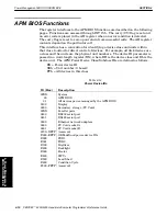
APM BIOS Functions
The register interfaces to the APM BIOS functions are described on the following
pages. Functions are accessed through INT 15h. The carry (CY) flag is set and
an error code is placed in the AH register when an error condition is detected.
The carry flag is reset to zero upon return from successful calls. The AH register
contents depend on the particular call.
This interface has a convention for identifying a device class and units within
that class to allow for direct control of devices. For example, all disk devices are
a class and the units are the physical unit numbers. The device ID parameter is
passed in a wordĆlength register (BX), where BH is the device class and BL is the
device unit. The APM Power Device Class/Subclass IDs are defined as follows:
BX = Power device ID
XXh = Unit number (0 based)
FFh = All devices in this class
Table 4Ć14
Power Device IDs
ID (Hex)
Description
00XX
System
00
APM BIOS
01
All devices powerĆmanaged by the APM BIOS
0100
Display
0200
Secondary storage (PC Card)
03XX
Parallel ports
0400
RS232 serial port
0401
RS485 serial port
0500
Ethernet network adapters
0600
PC Card socket A
0601
PC Card socket B
0700ćDFFF (reserved)
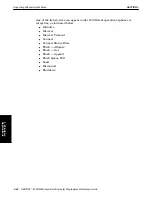
E000ćEFFF OEMĆdefined power device IDs
E000
POD1
E001
POD2
E100
Digitizer
E200
Backlight
E300
Heater
E400
SWV+
E500
Load Shed
E600
Condition Cycle
F000ćFFFF (reserved)
4. Power Management
BIOS: NORAPM.EXE

