Intermec EasyCoder 501 XP & 601 XP – Service Manual
114
Chapter 15
The CPU board is a four-layer board with most of its circuits sur-
face-mounted. On the front side is a combined circuit/GND layer,
inside the laminate are a VCC layer and a circuit layer, and on the
back side is a GND layer.
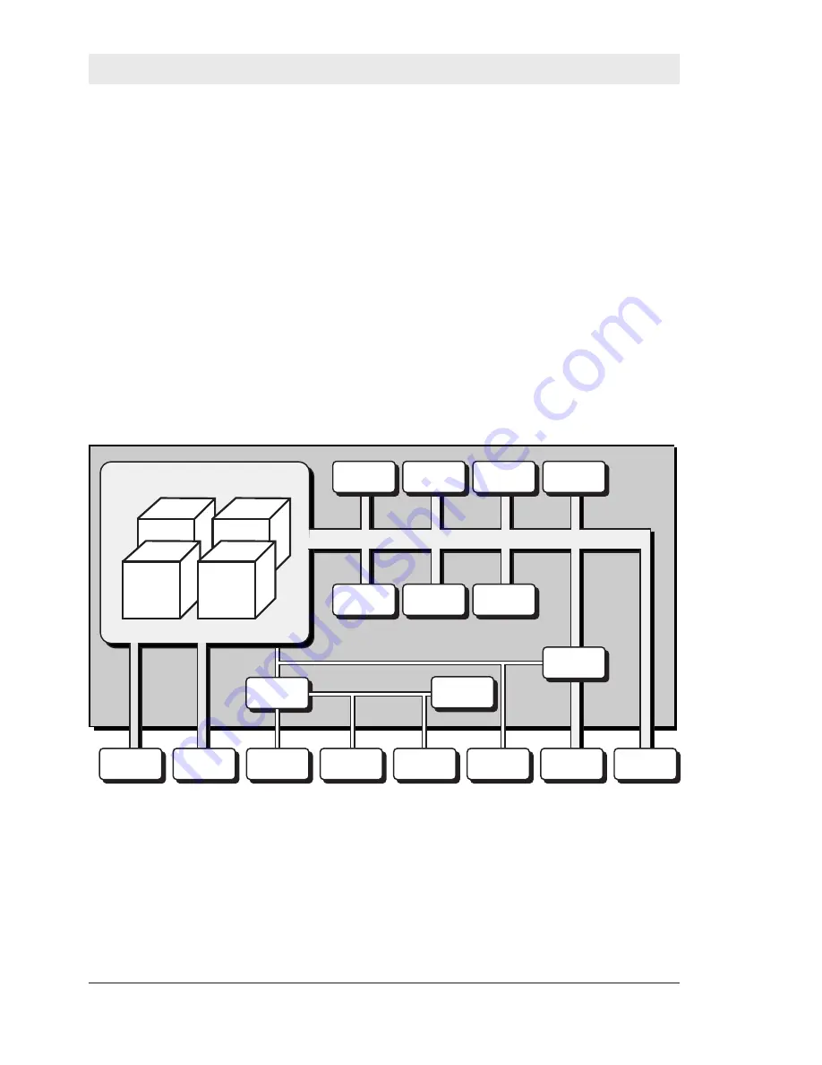
The hardware contains of the following main functions:
• A processor core.
• Stepper motor drivers.
• Thermal printhead driver.
• Sensor drivers.
• Peripheral units such as UART, Centronics, timers, etc.
• Flash memory SIMM for the fi rmware.
• DRAM SIMM
• Slave processor.
• Expansion bus.
15. CPU Board
15.1 Description
CPU
CORE
I2C-BUS
Clock
Support
Chip
Reset
&
Watchdog
I/O DATA
TPH
Logic
Timer
Stepper
Driver
Interrupt
Controller
Sensors
Memory
Card
Uart
Expansion
Bus
Flash
Memory
DRAM
Bar Code
Wand
Electronic
Key
Electronic
Key
Console
Optional
Board
Centronics
Slave Processor
A/D Converter
Electronic
Key/RTC


