Intermec EasyCoder 501 XP & 601 XP – Service Manual
136
Chapter 16 Interfaces
16.4 Fitting Optional
Interface Boards
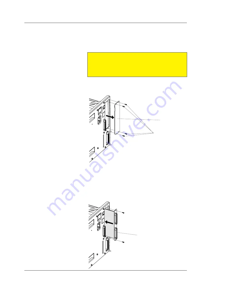
To install an optional interface board, proceed as follows (illustra-
tions show an Serial/Industrial Interface board.)
• Open the electronics compartment, see Chapter 13.3.
Warning!
Switch off the power and disconnect the power cord.
The electronics compartment contain high voltage components
and wires. Do not open the electronics compartment before the
printer is safely disconnected from any AC supply.
• Remove the four #T10 Torx screws that hold the interface cover
plate above the Centronics connector on the printer’s rear plate.
Remove the cover plate.
• Save the cover plate for possible later use. Keep the screws.
• If necessary, fi t or remove circuits and straps to adapt the inter-
face board according to the descriptions of each board later in
this chapter.
• Insert the interface board with the components side facing right,
as seen from behind. Check that the board fi ts into the two
square cut-outs on the left side of the slot.
#T10 Torx screws (4x)
Interface Board
Cover Plate


