background image

Intermec EasyCoder 601 XP – Installation & Operation Ed. 3

66

Chapter 8     Setup Mode

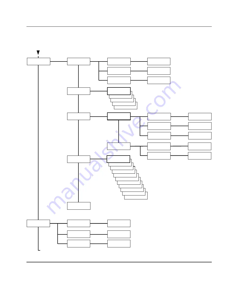
Setup Mode Overview, Part 2

(Intermec Fingerprint 7.12)

VAR LENGTH STRIP

FIX LENGTH STRIP

TICKET (w GAPS)

TICKET (w MARK)

MEDIA:
MEDIA SIZE

MEDIA:
CONTRAST

SETUP:
MEDIA

Use <F5> to select type of test label.
Press <Enter> to print it.
If no label is printed, press <F3> for error message. 

• Press Setup key to exit the Setup Mode.

MEDIA SIZE:
XSTART

MEDIA SIZE:
WIDTH

MEDIA SIZE:
LENGTH

XSTART:
[24]:

WIDTH:
[1960]:

LENGTH:
[1800]:

MEDIA:
MEDIA TYPE

MEDIA TYPE:
LABEL (w GAPS)

-2%

-4%

-6%

-8%

-10%

MEDIA TYPE:
+10%

+8%

+6%

+4%

+2%

CONTRAST:
+0%

PRINT DEFS:
HEAD RESIST

SETUP:
PRINT DEFS

HEAD RESIST:
[nnn]:

PRINT DEFS:
TESTPRINT

<ENTER> = PRINT:
<F5> = NEXT #1

Read-only value.
Printhead resistance is
automatically set at startup.

Continued from previous page!

PRINT SPEED:
[150]:

PRINT DEFS:
PRINT SPEED

TRANSFER:
RIBBON CONSTANT

TRANSFER:
RIBBON FACTOR

MEDIA:
PAPER TYPE

DIRECT THERMNAL:
LABEL CONSTANT

DIRECT THERMAL:
LABEL FACTOR

PAPER TYPE:
TRANSFER

PAPER TYPE:
DIRECT THERMAL

MEDIA:
TESTFEED

• Press Enter key to perform a Testfeed.
   Two or more copies will be fed out.
  

TRANSFER:
LABEL OFFSET

RIBBON CONSTANT:
[100]:

RIBBON FACTOR:
[25]:

LABEL CONSTANT:
[100]:

LABEL FACTOR:
[40]:

LABEL OFFSET:
[0]:

Summary of Contents for EasyCoder 601XP

Page 1: ...EasyCoder601XP BarCodeLabelPrinter P N 1 960430 03 Edition 3 September 1998 Installation Operation ...

Page 2: ... 8 2 Print a Label Introduction 9 Intermec Fingerprint 12 Intermec Direct Protocol 15 3 Installation Unpacking 16 Front View 17 Rear View 18 Media Compartment 19 Print Unit 20 Connections 21 Power 21 Computer 21 Controls and Indicators 22 Control Lamps 22 Display 22 Keyboard 22 Beeper 23 4 Starting Up Startup Files 24 Electronic Keys 24 Memory Cards 25 Power On 25 Display Messages at Startup 26 Ea...

Page 3: ...ion 51 Baudrate 51 Character Length 51 Parity 52 Stop Bits 52 Flow Control 52 New Line 53 Receive Buffer 53 Transmit Buffer 53 Feed Adjust 54 Startadjust 54 Stopadjust 54 Media 55 Media Size 55 Media Type 57 Paper Type 57 Contrast 59 Testfeed 60 Print Defines 60 Head Resistance 60 Testprint 60 Print Speed 60 8 Setup Mode Entering the Setup Mode at Installation 63 Navigating in Setup Mode 64 Setup ...

Page 4: ... Changing the Setup 75 Exiting Terminal Setup 76 Line Analyzer 77 10 Options Introduction 78 Peel Off Kit 79 Paper Cutter 79 Fan Fold Guides 80 3 Adapters 80 Paper Guide 80 Label Taken Sensor 80 Ribbon Low Sensor 81 EasySet Bar Code Wand 81 Interface Boards 81 11 Troubleshooting Troubleshooting list 82 12 Maintenance Printhead Cleaning 83 External Cleaning 87 Cleaning the Label Stop Sensor Guides ...

Page 5: ... registered trademark of Centronics Data Computer Corp Microsoft is a registered trademark of Microsoft Corporation Torx is a registered trademark of Camcar Division of Textron Inc TrueDoc is a registered trademark of Bitstream Inc TrueType is a trademark of Apple Computer Inc Unicode is a trademark of Unicode Inc Windows is a trademark of Microsoft Corporation Appendix 1 Technical Data 95 Appendi...

Page 6: ...a residential area is likely to cause interference in which case the user at his own expense will be required to take whatever measures may be required to correct the interference DOC Notice Canada Canadian Dept of Communication REGULATIONS COMPLIANCE DOC A This digital apparatus does not exceed the classAlimits for radio noise emissions from a digital appara tus as set out in the radio interferen...

Page 7: ...EasyCoder 601 XP to which this declaration relates is in conformity with the following standards Electrical Safety EN 60950 EMC Emissions EN 50081 1 92 EN 55022 94 class B EN 61000 3 2 95 EMC Immunity EN 50082 2 95 EN 61000 4 2 95 EN 61000 4 3 96 ENV 50204 95 EN 61000 4 4 95 EN 61000 4 6 96 following the provisions of Directives 89 336 EEC and 73 23 EEC Mölndal 1998 09 01 Hans Lindén President 1 I...

Page 8: ...l transfer printer for tear off operation An automatic paper cutter is available as an option and can be fitted by the user without any tools in a few seconds There is also an optional factory in stalled rewind unit for peel off operation The EasyCoder 601 XP supports the unique and flexible Intermec Fingerprint 7 12 programming language which allows the user to create custom made application prog...

Page 9: ...gerous voltage Do not put your fingers inside the print mechanism when the power is on Do not open the optional paper cutter when the power is on Place the printer on an even surface which can support its weight of 15 kgs 33 lbs plus supplies and possible options Do not spray the printer with water If using a hose to clean the premises in an industrial environment remove the printer or protect it ...

Page 10: ...the Intermec Fin gerprintprogramminglanguage Intermecalsoincludesprinterdriv ers for various versions of Microsoft Windows After having se lected the Windows Driver option in Intermec Shell you can use the EasyCoder 601 XP printer the same way as e g a laser printer and produce printouts from any standard program in MSWindows Connecting Printer and Host In the following examples we assume that you...

Page 11: ...st 40 mm 1 6 and a thermal transfer ribbon see chapters 5 and 6 If the printout becomes too light or dark you will need to change the paper type setup see chapter 8 Setup Mode Startup and Communications Check Turn on the printer Provided the printer is not fitted with any cus tom made startup program after initialization the display will show the Intermec Shell countdown menu ENTER SHELL 5 sec v 4...

Page 12: ...to feed out the paper and to pull it back Type FORMFEED 300 The printer will feed out a short piece of the label Then order the printer to pull back the label to its original position by typing FORMFEED 300 After loading a new supply of labels the printer should be allowed to adjust itself Type TESTFEED The printer will feed out at least two labels while adjusting its sen sors and paper feed mecha...

Page 13: ... wide with a 15 dot line thickness The box is inserted at position X 10 Y 10 NEW 10 PRPOS 10 10 20 PRBOX 430 340 15 200 PRINTFEED 300 END RUN Note The printer does not execute the program until you have typed RUN Printing an Image Now we add the image GLOBE 1 after changing the print coor dinates to X 30 Y 30 30 PRPOS 30 30 40 PRIMAGE GLOBE 1 RUN Printing a Bar Code To print a bar code you need to...

Page 14: ... Text Add text at position X 25 Y 220 80 PRPOS 25 220 90 FONT Swiss 721 BT 6 100 PRTXT My FIRST Label RUN Listing the Program To view the whole program type LIST The lines will be listed in ascending order on your terminal s screen 1 BARFONT ON 2 BARFONT Swiss 721 BT 6 10 PRPOS 10 10 20 PRBOX 430 340 15 30 PRPOS 30 30 40 PRIMAGE GLOBE 1 50 PRPOS 75 270 60 BARTYPE CODE39 70 PRBAR ABC 80 PRPOS 25 22...

Page 15: ...nd SAVE LABEL1 Your program will be saved in the printer s permanent memory un der the name LABEL1 PRG Loading the Program If you want to use this label later e g after having created more programs type LOAD LABEL1 PRG RUN A new copy of the label will be printed The Intermec Fingerprint offers a lot of more advanced func tionsthatallowsyoutocreatedsophisticatedapplicationprograms or to emulate oth...

Page 16: ...er BF ON enable bar code interpretation BF Swiss 721 BT 6 select bar code font PP 10 10 insertion point for box field PX 430 340 15 create a box PP 30 30 insertion point for image field PM GLOBE 1 select image PP 75 270 insertion point for bar code field BT CODE39 select bar code type PB VAR1 variable input data to bar code field PP 75 220 insertion point for text field FT Swiss 721 BT 6 select te...

Page 17: ...orderedoptions theboxshouldcontain Intermec EasyCoder 601 XP printer Adapters for 3 paper roll core 2 pcs Paper guide for label slack absorber Power cord Quality check card Cleaning card Approx 2 metres of labels Starter pack of thermal transfer ribbon User s Guide multilingual Installation Operation manual Setup bar codes sheet for EasySet wand Floppy disk with MS Windows printer drivers Check th...

Page 18: ...held by a snap lock Open the front door to view the various parts on the printer s front Keyboard Display Front Door Print Unit Connector for optional paper cutter Not used in this printer model Control Lamps Refer to chapter 10 Options for information on possible optional devices fitted on the printer s front ...

Page 19: ...sidential are a may cause harm ful interfere nce re quiring the user to take whatever steps may be necessary to correct the interfere nce C UL US LIS TED I T E 65B5 R Rear View The rear plate contains the main switch the power inlet and vari ous interface connectors Main Switch Mains Receptacle Memory Card Slot Machine Sign RS 232C Serial Interface uart1 Centronics Parallel Interface Provision for...

Page 20: ...I thermal transfer ribbons are engineered specifically for this printhead The quality of thermal and thermal transfer media supplies in this printer is also of great importance for the quality of printing bar codes and a long life of the printhead UBI has carefully matched the paper we recommend provide to the needs of this printer We therefore strongly advise of using only UBI recommended provide...

Page 21: ...gh performance 300 dpi thermal print head with quick mount fittings to facilitate replacement Thermal Printhead Dispenser Tear Off Edge Printhead Lift Arm Printhead Lift Knob Locking Handle Paper Guide Printhead Pressure Adjustment Lift Arm Locking Knob Label Stop Sensor Position Adjustment hidden behind locking handle ...

Page 22: ...he parallel interface with the Windows driver because it is faster than the serial interface There is no communication setup for the parallel interface RS 232 Serial Interface UsetheserialinterfacewithDirectProtocolorIntermecFingerprint programmingbecauseyoucanreceiveerrormessagesfromyour printer This is not available using the parallel interface Before you can use the serial interface you may nee...

Page 23: ...ground illumination and 2 lines of text each with 16 charac ters It guides the operator through the setup and informs him or her of possible errors during printing The Intermec Fingerprint programming language and the Intermec Direct Protocol allows custom made messages to be composed and displayed according to the requrements of the application The keyboard is of membrane switch type and has a se...

Page 24: ...dges that a key has been pressed The Intermec Finger print programming language allows the key acknowledge signal to be turned off The frequency and duration of the signal can be speci fied at will Thus it is possible create different signals for different conditions or even to make the printer play simple melodies Controls and Indicators cont d Beeper ...

Page 25: ... each of three different parts of the printer s memory If there are startup files stored in more than one place they will be used with the following priority 1 An autoexec bat file stored in any approved type of memory card provided it was inserted in the printer before power up 2 An autoexec bat file stored in the user s part of the printer s permanent memory device c 3 The pup bat file Intermec ...

Page 26: ...cally replaces the printer s firmware e g with an updated version Important Always turn off the power before inserting or removing a memory card Do not start the printer before you have made the necessary con nections inserted any memory card you want to use and checked that the printhead is lowered and the optional cutter is in closed position Turn on the power by means of the main switch on the ...

Page 27: ... shown in the display window directly after initialization A Intermec Shell Startup Program standard printers ENTER SHELL 5 sec v 4 2 4 sec v 4 2 3 sec v 4 2 2 sec v 4 2 1 sec v 4 2 Refer to chapter 9 for further information on Intermec Shell The digits in the lower right corner of the display indicate the version of Intermec Shell B Custom made Application Program non standard printers Any other ...

Page 28: ...rious forms This chapter describes the case when the paper strip is to be torn off manually against the printer s tear off edge Tear off can be used for Non adhesive continuous paper strip Self adhesive continuous paper strip Self adhesive labels on backing paper Tickets with gaps with or without perforations Tickets with marks with or without perforations Fold the locking handle downward outward ...

Page 29: ... paper core if any Tear Off cont d 4 5b 5a Fit a new paper roll on the paper supply spool and push the roll inwards as far as it will go In case of paper roll with a 76 mm 3 core first fit two adapters on the paper supply spool Turn the printhead lift knob to Open position 38 40 mm 1 5 76 mm 3 3 ...

Page 30: ...ob to Closed position 6 Tear Off cont d 7 8 9 Thread the paper through the print unit and push it inwards as far as it will go This diagram shows the path of the paper web Thread the paper underneath the slack absorber and forward towards the print unit The slack absorber can be rotated for better access ...

Page 31: ... 11 10 Tear Off cont d Adjust the position of the green paper guide so the paper is guided with a minimum of play 13 Return the locking handle to closed position Close the front and right hand doors Adjust the paper feed by simultaneously pressing the Shift and Feed keys Shift Feed ...

Page 32: ...Intermec EasyCoder 601 XP Installation Operation Ed 3 31 Chapter 5 Paper Load To tear off the paper grab the outer edge and pull downwards Tear Off cont d 14 ...

Page 33: ...ls on backing paper Note that the cutter must not cut through the labels only the backingpaper ortheadhesivewillsticktothebladesandrender the cutter inoperable or even damage the cutter s motor Tickets with gaps without perforations Tickets with marks without perforations CAUTION The rotating cutting blade can be accidently activated even when the cutter is opened To avoid any risk of injury to fi...

Page 34: ... 5 Paper Load 4 3 Remove the empty paper core if any Cut Off cont d 6a Fit a new paper roll on the paper supply spool and push the roll inwards as far as it will go Turn the printhead lift knob to Open position 5 Fold the locking handle downward forward 38 40 mm 1 5 ...

Page 35: ...rint unit and push it inwards as far as it will go In case of paper roll with a 76 mm 3 core first fit two adapters on the paper supply spool 6b 76 mm 3 Thread the paper underneath the slack absorber and forward towards the print unit The slack absorber can be rotated for better access This diagram shows the path of the paper web ...

Page 36: ...osition Thread the paper through the cutter between the two guide plates IM PORTA NT PRINTH EA D AND RI The use of any the rmal tra nsfer rib bons oth er tha n tho se su the pri nth ead wa rra nty UB I the rmal tra nsfer ribbons are en The quality of the rmal and the rmal tra nsfer me dia supplie for the quality of printing bar codes and a lon g life of the paper we rec om me nd pr ovide to the ne...

Page 37: ...r tha n tho se su the pri nth ead wa rra nty UB I the rmal tra nsfer ribbons are en The quality of the rmal and the rmal tra nsfer me dia supplie for the quality of printing bar codes and a lon g life of the paper we rec om me nd pr ovide to the needs of this print only UB I rec om me nded pr ovide d supplies to ensure a TEAR OFF Adjust the paper feed by simultaneously pressing the Shift and Feed ...

Page 38: ...n various forms This chapter describes the case when precut labels fitted on backing paper liner is to be separated from the backing paper after printing This requires an optional internal re wind unit on which the backing paper is rewound after the labels have been printed and dispensed Peel off can be used for Self adhesive labels fitted on backing paper Fold the locking handle downward outward ...

Page 39: ...pty paper core if any 3 Peel Off cont d 4 6a Fit a new paper roll on the paper supply spool and push the roll inwards as far as it will go Turn the printhead lift knob to Open position 38 40 mm 1 5 5 Pull out the green clip 1 on the backing paper take up and dispose of the backing paper 2 1 2 ...

Page 40: ...nwards as far as it will go 6b In case of paper roll with a 76 mm 3 core first fit two adapters on the paper supply spool 76 mm 3 Thread the paper underneath the slack absorber and forward towards the print unit The slack absorber can be rotated for better access Pull out approx 40 cm 15 of label web and remove the labels from the backing paper 40 cm 15 ...

Page 41: ...and he ne TEAR OFF Adjust the position of the green paper guide so the paper is guided with a minimum of play Peel Off cont d 10 11 12 13 This diagram shows the path of the labels and the backing paper Secure the backing paper with the clip 1 and rotate the spool so the web becomes tight 2 Thread the backing paper around the dispenser edge and back under the print unit 2 1 ...

Page 42: ...apter 5 Paper Load 16 15 14 17 Peel Off cont d Return the locking handle to closed position Turn the printhead lift knob to Closed position Adjust the paper feed by simultaneously pressing the Shift and Feed keys Close the front and right hand doors Shift Feed ...

Page 43: ...r enter the printer through either of the two slots in the rear plate it is recommended to fit the optional Intermec Fan Fold Kit which provides better guidance of the paper web using adjustable paper guides fitted to either the up per or lower slot in the rear plate When using an external paper supply take care to protect the paper from dust dirt and other foreign particles that can impair the pr...

Page 44: ...ion the printer can be fitted with a set of fan fold guides in either slot The outer guide is adjustable for different paper widths Fit the fan fold guide in the upper slot when the supply is at the same level as the printer Fit the fan fold guide in the lower slot when the paper supply is placed lower than the printer ...

Page 45: ... coated ribbon The thermal transfer printing allows a wide range of reciving face materials to be used Make sure to select a type of transfer ribbon that matches the type of receving face material to be used see Ap pendix 2 Media Specifications and to set up the printer accord ingly see chapter 7 Setting Up the Printer Transfer ribbons do not smear at room temperature NOTE Only original transfer r...

Page 46: ...Ribbon Load cont d Remove the used up ribbon and the empty ribbon core Unpack a roll of original Intermec thermal transfer ribbon In case of ribbon up to 60 mm 2 3 wide compress the bobbin and move it so it snaps into the first innermost groove 6a Turn the printhead lift knob to Open position 5 4 60 mm 2 3 1 ...

Page 47: ...s into the 3 rd groove 6b 6c 6d In case of 88 90 mm 3 5 ribbon width compress the bobbin and move it so it snaps into the 2 nd groove 6e 88 90 mm 3 5 2 110 mm 4 3 3 In case of 154 mm 6 0 ribbon width com press the bobbin and move it so it snaps into the 5 th groove In case of 130 mm 5 1 ribbon width com press the bobbin and move it so it snaps into the 4 th groove 130 mm 5 1 4 154 mm 6 0 5 ...

Page 48: ...he front end of the ribbon onto the take up spool Both spools should rotate counter clockwise Press the ribbon roll onto the ribbon supply spool 1 and thread the ribbon through the print unit Pull out approx 20 cm 8 of ribbon 2 Without releasing the ribbon turn the printhead lift knob to Closed position to lock the ribbon 9 166 mm 6 5 6 Ready Error Power EasyCoder 601 XP Print 3 6 8 9 7 Pause Setu...

Page 49: ...bbon Load cont d 11 12 13 Turn the printhead lift knob to Open position Wind up the ribbon until all of the transparent leader has passed the printhead and the ribbon becomes tight Turn the printhead lift knob to Closed position and close the locking handle Close the front and right hand doors 10 ...

Page 50: ...the Setup option in Intermec Shell to enter the Setup Mode Execute the Intermec Fingerprint SETUP instruction to enter the Setup Mode See chapter 8 Setup Mode in this manual In Intermec Shell UseTerminal Setup option to change the setup remotely from the host Note that Intermec Shell automatically sets up the printer in regard of communication when an application is selected See chapter 9 Intermec...

Page 51: ... Stopadjust 0 Media Contrast 0 X start 24 Width 1960 Length 1800 Media Type Label w Gaps Paper Type Thermal Transfer Ribbon Constant 100 Ribbon Factor 25 Label Offset 0 Print Defines Print speed 150 mm sec The printer s current setup values can be read from the display by browsing through the Setup Mode or from the host by browsing through the Terminal Setup of Intermec Shell You can list the prin...

Page 52: ...tion or for the IN and OUT ports on the optional Industrial Interface Board For each serial communication channel the following parameters can be set Make sure they match the setup of the connected device or vice versa If the setup of the printer and the setup of the host do not match the response from the printer to host will be garbled Baudrate The baudrate is the transmission speed in bits per ...

Page 53: ...indicates that the transmitting unit is able to receive characters RTS low indicates that the receive buffer is filled to 75 see XON XOFF CTS high indicates that the unit transmitting the CTS signal is readytoreceivedata CTSlowindicatesthatthereceivebufferis full see XON XOFF In some computer programs e g MS Windows Terminal RTS CTS is designated Hardware RTS CTS cannot be selected for any kind of...

Page 54: ... resumes transmitting data The same principles apply to XON XOFF sent by the host even if the percentage may differ By default XON XOFF is disabled for data both ways New Line This setup parameter allows you select the character s transmitted from the printer to specify the switching to a new line There are three options CR LF ASCII 13 dec ASCII 10 dec default LF ASCII 10 dec CR ASCII 13 dec Recei...

Page 55: ...edge of the copy than 15 mm 0 59 Stop Adjust The Stop Adjust value is given as a positive or negative number of dots 1 dot 0 083 mm 3 27mils Default value is 0 which stops the paper feed in a position suitable for tear off operation Apositivestopadjustmentmeansthatthenormalpaperfeed after theprintingiscompletedwillbeincreasedbythespecifiedvalue This case e g is suitable for use with a paper cutter...

Page 56: ...rint width Correspondingly changing the X start to less than the default value of 24 will make the inner mar gin smaller and increase the available print width Width Width specifies the width of the printable area and is defined as a number of dots from the origin The sum of the X start value and the width value gives the outer margin of the printable area The width must not be so large as to allo...

Page 57: ...ngth the paper feed is automatically stoppedtoavoidfeedingoutawholerollofpaper becauseofe g a blocked or faulty LSS By setting up the X start the Width and the Length you will create a print window inside which the printing can be performed Any object or field protruding outside the print window in any di rection will cause an error condition Error 1003 Field out of la bel Setup Parameters cont d ...

Page 58: ...ble paper errors Two different error conditions may occur Error 1005 Out of paper indicates that the last ordered copy could not be printed because of an empty paper stock Error 1031 Next label not found indicates that the last ordered labelorticketwassuccessfullyprinted butnomorelabels tickets can be printed because of an empty paper stock Paper Type The Paper Type setup controls the heat emitted...

Page 59: ... label material Thermal Transfer Printing Keep the Ribbon Factor for each quality at the recommended value Then decrease or increase the Ribbon Constant for lighter or darker images respectively For a new label material start with an average Ribbon Constant value for the ribbon quality in question Media cont d Thermal Transfer Printing Europe Ribbon Receiving Ribbon Ribbon Label Max Rec Print Spee...

Page 60: ...tion Constant Factor Picket Fence Bar Code Ladder Bar Code Top Coated Top Board 100 40 150 150 Standard Premium 95 40 200 200 Non Top Coated Economy 85 40 200 200 Standard Eco Board 80 40 200 150 Top Coated High Premium High Speed 80 30 225 225 Direct Thermal Printing North America DT Type Paper Label Label Max Rec Print Speed mm sec Speed Designation Constant Factor Picket Fence Bar Code Ladder B...

Page 61: ...lly at startup and can only be read Testprint A number of test labels can be printed Test label 1 4 are in tended for checking the printout quality and facilitate adjustment of the printhead pressure see chapter 13 Adjustments Test label 5 lists the printer s current setup an extra label will be printed if the printer is fitted an optional interface board The test labels are illustrated on next pa...

Page 62: ...asyCoder 601 XP Installation Operation Ed 3 61 Chapter 7 Setting Up the Printer Setup Parameters cont d Print Defines cont d Test Label 1 Test Label 2 Test Label 3 1160 ohms 12 dots CODE39 CODE39 1 234567 890128 ...

Page 63: ... LF REC BUF 300 TRANS BUF 300 PRINT CONFIG STARTADJ 0 STOPADJ 0 CONTRAST 0 XSTART 24 WIDTH 1960 LENGTH 1800 MEDIA TYPE LABEL w GAPS PAPER TYPE TRANSFER LABEL CONSTANT 100 LABEL FACTOR 40 RIBBON CONSTANT 100 RIBBON FACTOR 25 LABEL OFFSET 0 TESTFEED 12 3 HEAD RESIST 1109 PRINT SPEED 150 Odometer km 0 Model 601XP Hardware version 1 1 Ram 4096 k Fos 0 0 2048 k External 0 k FIRMWARE UBI Fingerprint 7 1...

Page 64: ...edanywherewithin Intermec Shell Set up the printer as described in this chapter Return to Intermec Shell by pressing the Setup key B EasyCoder 601 XP with no startup file installed Turn on the power IntheimmediatemodeofIntermecFingerprint pressthe Setup key Set up the printer as described in this chapter Exit to the immediate mode of Intermec Fingerprint by pressing the Setup key C EasyCoder 601 X...

Page 65: ...de 1 Left right up and down refer to the diagrams on the following pages Move up one level or scroll back in a stack of options1 Move one menu to the right on the same level1 Moveonemenutotheleftonthesamelevel1 Specify negative values leading position Enter numeric values Exit the Setup Mode Can be used anywhere in the Setup Mode Clear erroneously entered values Acknowledge and move to next menu P...

Page 66: ...R LF SER COM UART1 NEW LINE NEW LINE CR LF SER COM UART1 REC BUF REC BUF 300 SER COM UART1 TRANS BUF TRANS BUF 300 DETECTION FEEDADJ SETUP FEEDADJ FEEDADJ STOPADJ STOPADJ 0 STARTADJ 0 Continued on next page LEGEND Boxes with thick lines indicate default setup Boxes with dotted lines indicate menus related to optional interface boards FEEDADJ STARTADJ If an optional interface board is fitted commun...

Page 67: ...EDIA TYPE MEDIA TYPE LABEL w GAPS 2 4 6 8 10 MEDIA TYPE 10 8 6 4 2 CONTRAST 0 PRINT DEFS HEAD RESIST SETUP PRINT DEFS HEAD RESIST nnn PRINT DEFS TESTPRINT ENTER PRINT F5 NEXT 1 Read only value Printhead resistance is automatically set at startup Continued from previous page PRINT SPEED 150 PRINT DEFS PRINT SPEED TRANSFER RIBBON CONSTANT TRANSFER RIBBON FACTOR MEDIA PAPER TYPE DIRECT THERMNAL LABEL...

Page 68: ...ities Setup Mode manual setup from printer s keyboard Print Setup printing setup on label Testfeed formfeeds auto adjust of the LSS Test Label printing of test labels Default setup resetting all setup parameters to default Update PC card downloadingdatafromacomputertoaPC card inserted in the printer or upgrading the printer s firmware from a PC card Reboot restarting the printer Intermec Shell is ...

Page 69: ... This implies that if you use the same application all the time you will only need to turn on the power once the applica tion has been selected If no other application has been selected yet the default choice will be displayed when the countdown is completed e g FINGERPRINT 7 12 This message means that you have entered the immediate mode of Intermec Fingerprint with uart1 the standard RS 232C port...

Page 70: ...er and the computer normally uart1 For programming do not use the parallel centronics channel one way com munication only Refer to the Intermec Fingerprint manuals Intermec Direct Protocol is an easy to use printer protocol for down loading label layouts and variable input data to a printer from a host computer This option requires that you also select a standard IN OUT channel i e the channel you...

Page 71: ...es over and over again Press Enter for each new label Default Setup allows you to reset all setup parameters to their respective default values as listed in chapter 7 Software Update is used for two purposes Update PC card allows the printer to be used as a Flash PC cardprogrammingdevice BymeansoftheZmodemcommun icationtool filescanbedownloadedfromaPCtoaFlashPC card1 insertedinthememorycardslotint...

Page 72: ...ELL 5 sec v 4 2 ENTER SHELL 4 sec v 4 2 ENTER SHELL 3 sec v 4 2 ENTER SHELL 2 sec v 4 2 ENTER SHELL 1 sec v 4 2 Last selected application is started Default UBI Fingerprint w std I O uart1 Last selected application is started The selected application is started POWER ON Return to previous menu Proceed to next menu Accept displayed option and proceed or execute displayed option Perform a Testfeed a...

Page 73: ...he Setup Mode which you can enter by pressing the Setup key on the printer s built in keyboard Proceed as described in chapter 8 Setup Mode Among the facilities in Intermec Shell you will also find a number ofoptionsthatallowyoutoreadorchangethecommunicationsetup of the printer Setup This is another way of entering the Setup Mode where you can browsethroughthesetupparametersandmakechangesbymeans o...

Page 74: ... can be found in Chapter 7 Setting Up the Printer When you transmit the triple T TTT or ttt to the printer the fol lowing message will appear on printer s display SETUP FROM TERMINAL On the screen of the host another message will appear Welcome to SHELL v 4 2 in terminal mode Answer Y CR for Yes CR for No SHELL SEL APPLICATION Y N B From here on you can move around in Intermec Shell according to t...

Page 75: ...gerprint application SHELL SEL APPLICATION Y N B Y SEL APPLICATION CURRENT APPL Y N B N SEL APPLICATION LABELSHOP Y N B N SEL APPLICATION WINDOWS DRIVER Y N B N SEL APPLICATION Fingerprint 7 12 Y N B Y STD I O CHANNEL UART1 Y N B Y When you have answered the final prompt the printer will start the selected application Terminal Setup cont d Selecting an Application ...

Page 76: ...l according to the same principles as when using the printer s own keyboard see overviews in chapter 8 Key Action u Move one menu to the left on the same level same as F1 d Move one menu to the right on the same level same as F2 e Display error message at test label printing failure same as F3 b Move up one level or scroll back in a stack of menus same as F4 f Move down one level or scroll forward...

Page 77: ... e g after having changed the setup youmustselecttheRebootoptionafterhavingsteppedthrough all the facility options as illustrated below SHELL PRINT SETUP Y N B N SHELL TESTFEED Y N B N SHELL TEST LABEL Y N B N SHELL DEFAULT SETUP Y N B N SHELL SOFTWARE UPDATE Y N B N SHELL REBOOT Y N B Y Terminal Setup cont d Exiting Terminal Setup ...

Page 78: ...econds the program considers the transmission termi nated and prints out a label As long as a continuous string of characters is being received the program wraps the lines until the label is full and then starts to print another label At the bottom of each label the following informa tion is printed Page number Number of characters printed on the label Total of characters received so far The Line ...

Page 79: ...ble for EasyCoder 601 XP IM PORTANT PRINTHEAD AND RIBBON INFORMATION The use of any thermal transfer ribbons other than those supplied by UBI will invalidate the printhead warranty UBI thermal transfer ribbons are engineered specifically for this printhead The quality of thermal and thermal transfer media supplies in this printer is also of great importance for the quality of printing bar codes an...

Page 80: ...be used to cut through any kind of adhesive which would stick to the cutting parts and rapidly render the cutter inoperable possi bly also causing damage to the electric motor Maximum paper thickness is 175 µm 175 grammes m2 for nor mal paper based materials The paper cutter increases the printer s total weight by approx 1 65 kgs 3 6 lbs and its length by 28 mm 1 1 The paper cutter can be tilted f...

Page 81: ... each delivery of the EasyCoder 601 XP and makes it possible to use paper rolls with 3 inch 76 mm inner diameter paper cores The adapters are pressed onto the paper supply spool and held in placebyscrews Whenfittingtheadapters makesurethatthescrews hit a rounded plastic surface not the metal leaf springs Illustrations of how to load the paper using the adapters are to be found in chap ter 5 Paper ...

Page 82: ...can also be used to read other CODE 128 bar codes as input data to a Intermec Fingerprint program For further information on how to compose setup bar codes see the Intermec Fingerprint 7 12 Reference Manual Asheet with a collec tion of printed bar codes for various setup parameters is delivered with the printer The bar code wand is connected to the topmost connector on the printer s rear plate imm...

Page 83: ...nthead voltage Replace CPU board Call Service Excessive bleeding Wrong Paper Type setup Change setup Chapter 7 Contrast setup value too high Change setup Chapter 7 Printhead pressure too high Adjust Chapter13 Faulty energy control Replace CPU board Call Service Transfer ribbon breaks Ribbon fitted around label stop sensor Reload ribbon Chapter 6 Wrong Paper Type setup Change setup Chapter 7 then c...

Page 84: ... the life of the printhead and for the printout quality Below is a description on how to clean the printhead by means of Cleaning Cards If addi tional cleaning is required e g for removing adhesive residue from the print roller or dispenser edge use a cotton swab moistened with isopropyl alcohol Caution Isopropyl alcohol CH3 2 CHOH CAS 67 63 0 is a highly flammable moderately toxic and mildly irri...

Page 85: ...o u ch an d re m o v e E as y C o d er C le an in g C ar d L if t th er m al p ri n th ea d an d in se rt E as y C o d er C le an in g C ar d L o w er p ri n th ea d an d p re ss F E E D o r P R IN T If p ri n te r re tu rn s an er ro r m es sa g e re p ea t th e p ro ce d u re b u t p re ss F E E D o r P R IN T b ef o re lo w er in g th e p ri n th ea d T h e p ri n te r w il l st ar t fe ed in g...

Page 86: ...nder the printhead 1 again Close the printhead 2 Printhead Cleaning cont d 7 8 9 10 Wait for appox 30 seconds to allow the clean ing fluid to dissolve the residue 12 11 10 9 8 7 6 5 4 3 2 1 30 s Pull out the cleaning card If necessary repeat the process with a new cleaning card Pull out the cleaning card 1 and open the printhead 2 ...

Page 87: ...Coder 601 XP Installation Operation Ed 3 86 Chapter 12 Maintenance Printhead Cleaning cont d 11 Allow the cleaned parts to dry before loading paper and transfer ribbon 12 Return the locking handle to closed position ...

Page 88: ...lways remove the power cord before cleaning Wipe external surfaces with a soft cloth mois tened with water and if necessary a mild detergent Never spray the printer Protect it from water when cleaning the premises Never use any sharp tools for removing stuck labels The printhead and rollers are delicate 4 ...

Page 89: ...dows through which the light from two parts of the label stop sensor is transmitted These windows must be kept clean from dust stuck labels and adhesive residue If the printer starts to feed out labels in an unexpected way remove these two guides as described below and check for anything that may block the beam of light If necessary clean them using a clean ing card or a soft cloth soaked with iso...

Page 90: ...g and cooling processes during printing Thus the printhead will require periodical replace ment Time between printhead replacements depends on the print images the type of ribbon or paper in use the amount of energy to the print head and several other factors Note While replacing the printhead the power should be switched off 2 1 Open the front and right hand doors Fold the locking handle downward...

Page 91: ...eplacement cont d 3 4 5 6 Remove the paper and transfer ribbon if any Pull the printhead bracket away from the magnet in the lift arm Disconnect the hooked printhead bracket fingers from shaft and pull out the printhead as far as the cables allow Turn the printhead lift knob to Open position ...

Page 92: ... Blue connector to the left white connector to the right Fit the hooks of the printhead bracket fingers onto the headlift shaft Close the printhead so the magnet engages the printhead bracket Close the locking handle 10 Blue White Disconnect the two cables from the printhead Note the snap lock on the white connector Pull at the connectors not the cables Snap lock ...

Page 93: ...see chapter 7 Setting Up the Printer and check the print out Increased pressure generally gives a darker printout and vice versa Repeat until the desired result is obtained To find the basic setting turn the knob counter clockwise until there is no pressure left Test with a piece of paper under the printhead you should be able to pull it out without more than just a little resist ance Then turn th...

Page 94: ...aper Similarly when revert ing to a wider paper the arm should be adjusted or the printout on the outer part of the paper could be weak To adjust the printhead lift arm proceed as follows Remove the ribbon if any Loosen the knob that holds the lift arm Move the arm inwards or outwards until the arrow on the tip of the arm becomes centre aligned with the paper web Whilemovingthearm pushatthepartwhe...

Page 95: ...e outer lower ga ble Turning the screw clockwise will move the LSS inwards and vice versa The position of the LSS in relation to the paper is best checked by looking head on into the print unit when the printhead is lifted Align the centrepoint of the V shaped upper sensor with the centre of the slots or marks to be detected The linear markings on the lower guide plate can also be used for positio...

Page 96: ... Off Optional With cutter Firmware Operating System Intermec Fingerprint 7 12 incl Direct Protocol Smooth Fonts TrueDoc and TrueType fonts Built in fonts std 15 UNICODE Latin fonts Built in bar code symbologies std 36 Startup Program std Intermec Shell 4 2 Physical Measures Dimensions W x D x H 335 x 482 x 238 mm 13 1 x 19 0 x 9 4 Weight excluding media options 15 kgs 33 lbs Ambient Operating Temp...

Page 97: ... Bar Code Wand Yes For setup Electronic Keys 1 2 Future option Connection for Optional Interface Boards 1 Memory Card Adapter 1 Flash or SRAM cards Accessories MS Windows Printer Drivers excl cable Yes For various versions Automatic Paper Cutter Option Internal Rewind Unit Option factory installed only For peel off operation Fan Fold Guides Kit Option For external supply RS 232C Cable Option Centr...

Page 98: ...rmec offers stock labels for thermal transfer printing in a wide range of qualities Uncoated papers for economical high volume printing in combination with GP Standard ribbons Examples Vellum Duratran I Coatedpaperswithvariouscoat weight smoothnessandglossto beusedwithHP PremiumandGP Standardribbons Examples Matte Coated Duratran VG Transfer Premium Duratran II Premium Tag Duratran II Tag High Glo...

Page 99: ...he core in such a way that the printer can pull the end of the web free Otherwise the thermal transfer ribbon may be damaged Roll Max diameter 205 0 mm 8 07 Max width 168 0 mm 6 61 Min width 76 2 mm 3 Max web thickness 175 µm 0 007 The maximum recommended web thickness is 175µm A thicker web may be used but print quality will be reduced Web stiffness is also important and must be balanced against ...

Page 100: ...601 XP Installation Operation Ed 3 99 Appendix 2 Media Specifications Non Adhesive Strip Paper a Web Width Maximum 168 0 mm 6 61 Minimum 76 2 mm 3 00 Media Type Setup Fix lenght strip Var lenght strip a NON ADHESIVE STRIP ...

Page 101: ...The backing paper must not extend more than a total of 1 6 mm 0 06 outside the paper and should protrude equally on both sides c Paper Width excluding backing paper Maximum 166 4 mm 6 55 Minimum 74 6 mm 2 94 Media Type Setup Fix lenght strip Var lenght strip Note This type of paper is not suitable for use with a paper cutter Self Adhesive Strip Paper cont d b a SELF ADHESIVE STRIP c c ...

Page 102: ...e circumstances a minimum label length down to 4 mm 0 16 could be used It requires the sum of the label length d and the label gap e to be larger than 7 mm 0 28 that batch printing is used and that no pull back of the paper is performed Intermec does not guarantee that such short labels will work but it is up to the user to test this in his unique application e Label Gap Maximum 21 3 mm 0 83 Recom...

Page 103: ... to the user to test this in his unique application c Detection Slit Start The restriction of the minimum detection slit length must be ob served and the slit must not break the inner edge of the web d Detection Slit Length The length of the detections slit excluding corner radii must be Minimum 5 0 mm 0 20 e Detection Slit End Provided the restrictions of the minimum slit length and slit start ar...

Page 104: ... 3 mm 0 83 Common 12 5 mm 0 5 Minimum 5 0 mm 0 2 g Black Mark Y Position It is recommended to place the black mark as close to the front edge of the ticket as possible and use a negative Stop Adjust value to control the paper feed so the tickets can be properly torn or cut off Media Type Setup Ticket w mark Important Preprintthatmayinterferewiththedetectionoftheblack mark should be avoided on the ...

Page 105: ...P Premium transfer ribbons allow high speedprintingandgivesahighlyreadableanddefinedprintouton most face materials with smooth surfaces They have good smear resistance and are most suitable for intricate logotypes and images on matte coated papers and synthetic face materials High Resistance HR Super Premium transfer ribbons give an extremely durable printout which is resistant to most chemical ag...

Page 106: ...erial interface settings see chapter 7 Setting Up the Printer Interface Cable Computer end DB9 or DB 25 female connector PC Printer end DB25 female connector Host EasyCoder 601 XP Host Signal DB 9 DB 25 Signal DB 25 DB 25 Signal 1 1 1 1 shield RXD 2 2 TXD 2 3 RXD TXD 3 3 RXD 3 2 TXD CTS 8 4 RTS 4 5 CTS RTS 7 5 CTS 5 4 RTS 6 DSR 6 20 DTR GND 5 7 Signal GND 7 7 GND 16 5V1 16 DSR 6 20 DTR 20 6 DSR 22...

Page 107: ...K and BUSY signals when respond ing to host data is 2500 ns ACK BUSY inactivated as soon as ACK pulse starts Classic type Centronics Predefined timing for the ACK and BUSY signals when respond ing to host data is BUSY deactivated wait 2500 ns then give 2500 ns pulse on ACK Select the desired device as standard IN channel by means of a SETSTDIO statement2 By default uart1 is STD I O Interface Cable...

Reviews: