background image

Chapter 4 — ED40 Setup

ED40 Decode Board Integration Guide

23

Basic Setup with Configuration Bar Codes

This section provides you with the bar codes necessary for a basic setup. For 
advanced setup options, see 

“Advanced Setup with Configuration Bar Codes” 

on page 30

. For all setup options use EasySet.

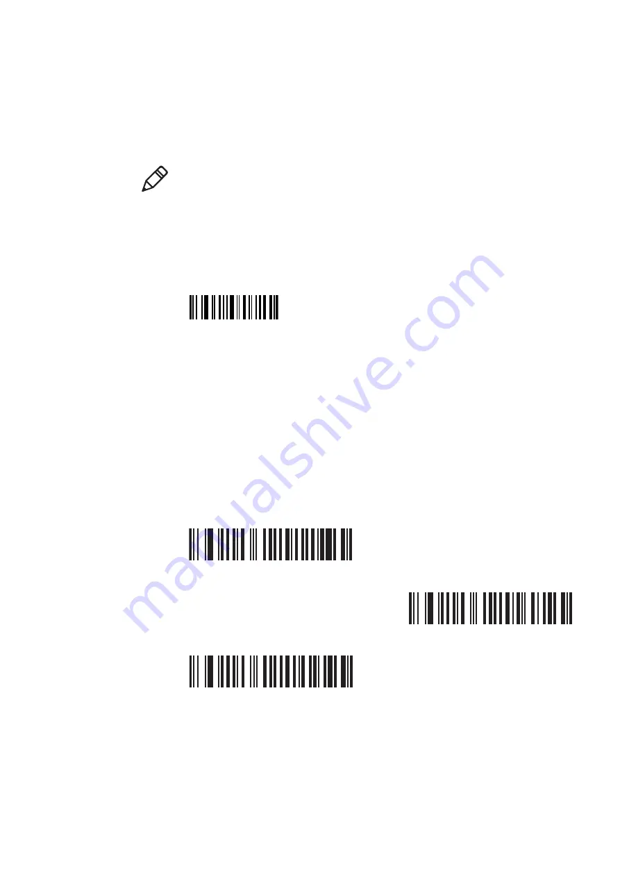
Reset Factory Defaults

Before setup you may need to reset the factory defaults in your ED40 for a fresh 
start. This bar code resets factory defaults for all parameters except locked 
parameters.

Interface

Depending on the interface used, you may need to setup the parameters for 
communication. 

RS-232 Interface Parameters

The default RS-232 settings are 57600 baud rate, 8 data bits, and no parity. Data 
bits and parity are fixed ISCP parameters that can only be changed when ISCP is 
not active. An asterisk symbol (*) indicates the default value. 

Baud Rate

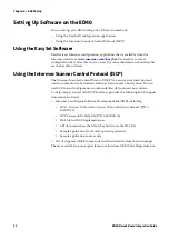
Scan one of these bar codes to set the baud rate.

Note:

 All default values in this section are indicated with a (*).

Reset factory defaults

CCMD 40 06

38400

SW 63 40 09

57600 (*)

SW 63 40 0A

115200

SW 63 40 0B

Summary of Contents for ED40

Page 1: ...Decode Board Used with EA11 EA20X EA21 and EA30 Imagers ED40 Integration Guide EA11 EA20X EA21 EA30 ...

Page 2: ...ent a commitment on the part of Intermec Technologies Corporation 2010 2011 by Intermec Technologies Corporation All rights reserved The word Intermec the Intermec logo Norand ArciTech Beverage Routebook CrossBar dcBrowser Duratherm EasyADC EasyCoder EasySet Fingerprint INCA under license i gistics Intellitag Intellitag Gen2 JANUS LabelShop MobileLAN Picolink Ready to Work RoutePower Sabre ScanPlu...

Page 3: ...ions Added hibernate mode information B 04 2011 Corrected regulatory information Added EA30 imager appendix including information on setting up motion tolerance Corrected EA21 mounted imager position graphic position 1 and 2 were switched Added inrush current graphics for EA11 EA20X EA21 and EA30 Changed instructions for downloading the USB driver Added information on Video and ISCP configuration ...

Page 4: ...iv ED40 Decode Board Integration Guide ...

Page 5: ...anical Dimensions 6 Ribbon Cable 6 Ribbon Cable Connecting the Decode Board to the Host 7 Connecting the Ribbon Cable 8 3 Electrical Integration 11 General Information 12 Electrical Characteristics 12 Power Supply Noise 12 Thermal Considerations 13 EMI Recommendations 13 Grounding the Metal Shield 13 Grounding the ED40 13 Connecting the ED40 to the Host 14 RS 232 Interface 14 USB Interface 15 Elec...

Page 6: ...D 37 Hibernate Mode 37 5 Firmware Download 39 Connections for Firmware Download 40 RS 232 Interface 40 USB Interface 41 Downloading Firmware 42 Initializing Download Mode 42 Hardware Initialization in an RS 232 Interface 42 Hardware Initialization in a USB Interface 42 Software Initialization 42 Baud Rate Auto Detect 43 Dialog Between Host and Imager 43 Downloading the Flash Driver 43 Dialog Betwe...

Page 7: ...ve Idle to Scan Inrush Current 68 Scanning Current 68 Hibernate Current 69 Using a USB Cable 69 Power Up with Vcc Inrush Current 69 Power Up with Power Enable Inrush Current 1 70 Power Up with Power Enable Inrush Current 2 Zoom 70 Power Up Vcc Inrush Current to Active Idle 71 Active Idle to Scan Inrush Current 71 Scanning Current 72 Mechanical Dimensions 73 Mounting and Positioning Holes 74 Mounte...

Page 8: ...the Ribbon Cable 96 Imager Connector Contact Assignment 97 C EA21 Imager 99 EA21 Imager Features 100 EA21 ED40 Views 100 EA21 Reading Distances 101 Typical Reading Distances 101 Minimum Reading Distances 102 Operational Current 103 EA21 ED40 Inrush Currents 104 Using an RS 232 Cable 104 Power Up with Vcc Inrush Current 104 Power Up with Power Enable Inrush Current 105 Power Up Vcc Inrush Current t...

Page 9: ...urrent to Active Idle 125 Active Idle to Scan Inrush Current 126 Scanning Current 126 Hibernate Current 127 Using a USB Cable 127 Power Up with Vcc Inrush Current 127 Power Up with Power Enable Inrush Current 1 128 Power Up with Power Enable Inrush Current 2 Zoom 128 Power Up Vcc Inrush Current to Active Idle 129 Active Idle to Scan Inrush Current 129 Scanning Current 130 Motion Tolerance 131 Peak...

Page 10: ...d programs The code is provided as is with all faults All warranties are expressly disclaimed including the implied warranties of merchantability and fitness for a particular purpose A warning alerts you of an operating procedure practice condition or statement that must be strictly observed to avoid death or serious injury to the persons working on the equipment A caution alerts you to an operati...

Page 11: ...Regulatory Information The ED40 is a component and thus the final manufacturer is responsible for compliance with regulatory standards that apply U S A Canada This product has been designed to comply with the FCC Federal Regulation 47 CFR Part 15 Subpart B for Class B computing devices It is the manufacturer s responsibility to test the final product for compliance with this and other regulations ...

Page 12: ...ctual property rights belonging to Intermec Technologies Corporation The application of this component could infringe on the intellectual property of Intermec Technologies Corporation or their companies and licenses for use must be sought as appropriate Intermec Technologies Corporation does not assume any product liability in connection with integrating this component within any sub assembly syst...

Page 13: ...roducing the ED40 Decode Board This chapter provides an introduction to the ED40 decode board and contains these sections What is the ED40 Decode Board ED40 Views Handling Precautions Technical Specifications ...

Page 14: ...family of imager engines It is used to control the imager capture images and decode 1D and 2D bar codes The ED40 decode board can be used with the following Intermec imager engines EA11 EA20X EA21 EA30 ED40 Views ED40 Decode Board The ED40 can be used as a one piece mounted design or a 2 piece unmounted design as shown in the drawing below Imager connector Host connector ...

Page 15: ...ing bracket EA11 imager ED40 decode board ribbon cable EA11 imager Mounted Unmounted Integrated circuits on the printed circuit board PCB are very sensitive to damage by electrostatic discharge ESD Follow standard ESD guidelines to avoid damaging the equipment you are servicing Because finger oils can impede the performance of scanner parts and dissolve the reflective coating of the plastic mirror...

Page 16: ...nse Image Format Raw JPEG TIFFG4 Electrical Characteristics Operating Voltage 3 0 V to 5 5 V Operating Current Depends on the imager see the appendix for your imager Environmental Characteristics operating temperature 20 C to 60 C 4 F to 140 F except in continuous operation see Thermal Considerations on page 13 storage temperature 30 C to 70 C 22 F to 158 F relative humidity 0 to 95 non condensing...

Page 17: ...5 2 Mechanical Integration This section provides the information needed to successfully integrate the ED40 decode board Mechanical Dimensions Ribbon Cable ...

Page 18: ...e imager to the ED40 decode board This section will give information only on the ribbon cable connecting the ED40 to the host 34 mm 1 34 in 19 mm 0 75 in 5 6 mm 0 22 in 2 mm 0 08 in 2 mm 0 08 in 2 0 mm 0 08 in 2 0 mm 0 08 in 30 mm 1 18 in Diameter 1 7 mm 0 07 in 2 places with ground fill around the holes Imager Connector Host Connector Note For information on the ribbon cable connecting the imager ...

Page 19: ...iew and side view of the ribbon cable from the ED40 decode board to the host Intermec recommends that you specify the resistance for the PIN 1 Vcc and PIN 7 GND conductors to be less than 0 1 ohm To avoid corrosion caused by dissimilar metals Intermec recommends using a ribbon cable with gold plated contacts Corrosion can create a barrier between the connector contacts and the ribbon cable contact...

Page 20: ...st connector To connect the host connector 1 Open the connector clip Use a small screwdriver or other pointed object to push on the edge of the clip and extend it The voltage at the ED40 contacts must be at least 3 0V At any lower voltage you will not have a reliable connection Also be sure to consider line drop across the flex cable which can be substantial Do not disconnect ribbon cables while p...

Page 21: ...40 Decode Board Integration Guide 9 2 Insert the ribbon cable Make sure that the contacts are facing the board and that the connectors on the ribbon cable are touching the connectors on the imager 3 Close the connector clip Ribbon cable ...

Page 22: ...Chapter 2 Mechanical Integration 10 ED40 Decode Board Integration Guide ...

Page 23: ...11 3 Electrical Integration This chapter provides the information on the electrical integration of your imager It contains the following sections General Information Electrical Interface ...

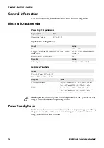
Page 24: ...ue Operating Voltage 3 0 V to 5 5 V Input Output Voltage Ranges Inputs Value Vcc 3 V to 5 5 V Trigger Power Enable Detect In 1 CTS Detect In 2 Detect In 0 3 V to 5 V 5 V tolerant even if Vcc is 3 V RXD USB D TXD USB D 3 3 V Outputs Value All outputs 3 3 V even if Vcc is 5 V Logic Level Thresholds Inputs Vih 2 0 V min Vcc 3 0 V Vil 0 8 V max Vcc 3 0 V Outputs Value TXD LED Buzzer Voh 2 4 V min Vcc ...

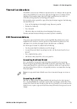
Page 25: ...nformation is valid for all imagers EA11 EA20X EA21 and EA30 For all imagers Intermec recommends the following Use the metal shield included around the imager Ground the metal shield mounting bracket and the decode board to host ground Use a shielded ribbon cable All ribbon cables should be as short as possible Grounding the Metal Shield For a mounted scan engine the metal shield is grounded via t...

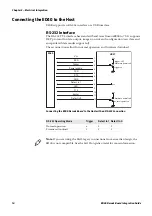
Page 26: ...ons allow for normal operation and firmware download Connecting the ED40 Decode Board to the Host with an RS 232 Connection RS 232 Operating Mode Trigger Detect In 1 Detect In 0 Normal operation x 1 0 Firmware download 1 1 1 ED40 HOST 1 2 3 4 5 6 7 8 9 10 11 12 RXD Trigger Power enable TXD RTS GND Detect in 1 LED CTS Buzzer Detect in 0 Vcc trigger on Vcc trigger off firmware download Vcc Vcc normal...

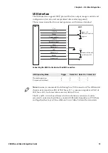
Page 27: ... 1 0 1 ED40 HOST 1 2 3 4 5 6 7 8 9 10 11 12 USB D Trigger Power enable USB D Do not connect GND Detect in 1 LED Detect in 2 Buzzer Detect in 0 Vcc trigger on Vcc trigger off firmware download Vcc Vcc normal operation firmware download Note Intermec recommends the following for a USB connection The differential characteristic impedance Z0 of 90 Ohms 15 a common impedance ZCM of 30 Ohms 30 and a maxim...

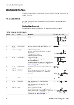
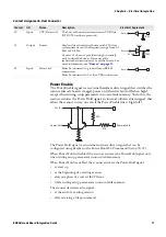
Page 28: ...on Stops reading and decoding 4 Input Power Enable 0 On active idle 1 Off except when writing setup parameters to non volatile memory To conserve power set contact 4 to high when not scanning For more information see Power Enable on page 17 5 Input Output TXD USB D Serial output transmission to host USB data minus 6 Output RTS NC Used to request permission from the host to transmit on TXD line RTS...

Page 29: ... activates the Power Hold signal at start up at the beginning of a reading session after reception of a correct ISCP frame while writing setup parameters in non volatile memory The scanner deactivates the signal at the end of a reading session after receiving a Sleep command 10 Input CTS Detect in 2 The host authorizes transmission on TXD line RTS CTS hardware protocol 11 Output Buzzer Used to dri...

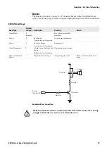
Page 30: ...n Meaning Action Good Read 1 default LED flash Bar code successfully decoded Setup 2 Fast flashes Setting up parameters Error 6 Very fast flashes Setup error User Permission 9 3 long flashes followed by an Error flash User permission denied Setup Checksum Error Repetitive Error flashes Setup integrity error Reset to factory defaults to stop VCC Resistor LED Resistor LED Contact 9 Transistor Make s...

Page 31: ...lt Bar code successfully decoded Setup 2 Fast beeps Constant tone frequency Setting up parameters Error 6 Very fast beeps Constant tone frequency Setup error User Permission 9 3 long beeps then very fast beeps Different tone frequency User permission denied Setup Checksum Error Repetitive Error beeps Setup integrity error Reset to factory defaults to stop Resistor Resistor Buzzer Capacitor VCC Buz...

Page 32: ...Chapter 3 Electrical Integration 20 ED40 Decode Board Integration Guide ...

Page 33: ...chapter describes how to setup the ED40 decode board and includes these sections Setting Up Software on the ED40 Basic Setup with Configuration Bar Codes Advanced Setup with Configuration Bar Codes Test Bar Codes Operation ...

Page 34: ...l Protocol ISCP is a secure structured protocol used to communicate between an Intermec scanner and a host system You can use ISCP to send configuration commands directly from your host system To help you get started with ISCP Intermec provides the following ISCP support documents and tools Intermec Scan Engine Software Development Kit SDK including ISCP Structure Frame Descriptions Technical Refe...

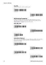
Page 35: ... resets factory defaults for all parameters except locked parameters Interface Depending on the interface used you may need to setup the parameters for communication RS 232 Interface Parameters The default RS 232 settings are 57600 baud rate 8 data bits and no parity Data bits and parity are fixed ISCP parameters that can only be changed when ISCP is not active An asterisk symbol indicates the def...

Page 36: ... page 37 for more information USB Cable Mode International Keyboard Select your international keyboard if using USB Keyboard HID cable mode This setting does not apply to USB Virtual COM For additional international keyboards see EasySet 1 SW 63 44 00 2 SW 63 44 01 USB Virtual COM SW 68 40 02 USB Keyboard HID SW 68 40 00 USB Virtual COM Video SW 68 40 03 North American Windows SW 67 40 00 French W...

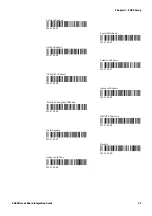
Page 37: ...anish Windows SW 67 40 05 Italian Windows SW 67 40 06 Swedish Windows SW 67 40 07 UK English Windows SW 67 40 08 Japanese Windows SW 67 40 09 Brazilian Portuguese Windows SW 67 40 0A IBM NCR Terminals SW 67 40 0B Czech Republic SW 67 40 0C Slovakia SW 67 40 0D Hungarian 101 key SW 67 40 0E ...

Page 38: ...e type of bar code environment and reading surface There are 4 pre defined imager settings 1 Dimensional bar codes only Standard 1 dimensional and 2 dimensional bar codes 1 Dimensional and 2 dimensional bar codes in a bright environment 1 Dimensional and 2 dimensional bar codes with reflective surface shiny labels Select the pre defined imager setting that best suits your needs None SW 60 C1 00 00...

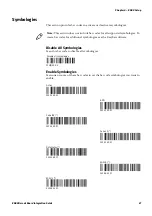
Page 39: ...le Symbologies Scan one or more of these bar codes to set the bar code symbologies you want to enable Note This section does not include bar codes for all supported symbologies To create bar codes for additional symbologies see the EasySet software Disable all symbologies CCMD 40 03 Aztec SW 53 40 01 BPO SW 32 40 01 Code 128 SW 43 40 01 Code 39 SW 42 40 01 DataMatrix SW 54 40 01 EAN 8 SW 4B 42 01 ...

Page 40: ... Composite CC AB SW 56 40 01 GS1 Composite CC C SW 56 41 01 GS1 DataBar Omni Directional SW 4F 40 01 GS1 DataBar Expanded SW 4F 42 01 GS1 DataBar Limited SW 4F 41 01 Interleaved 2 of 5 SW 44 40 01 PDF 417 SW 4C 40 01 Postnet SW 30 40 01 QR Code SW 55 40 01 Standard 2 of 5 SW 48 40 01 ...

Page 41: ...Chapter 4 ED40 Setup ED40 Decode Board Integration Guide 29 UPC A SW 4B 40 01 UPC E SW 4B 41 01 ...

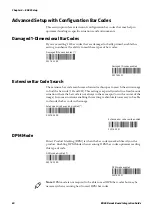
Page 42: ...g is especially useful in a fixed mount situation where the bar code is not always in the same spot or in the center of the image In some situations enabling this setting is absolutely necessary to be able to decode the bar code in the image DPM Mode Direct Product Marking DPM is when the bar code is marked directly on the product Enabling DPM Mode when scanning DPM bar codes optimizes reading thi...

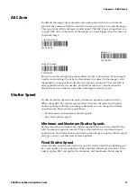
Page 43: ...Shutter Speed By default shutter speed is automatic automatic exposure control or AEC When using AEC the shutter speed will vary between the lowest and highest shutter speeds possible for your imager However you can change the shutter speed settings There are two possibilities Set minimum and maximum shutter speeds Set a fixed shutter speed Minimum and Maximum Shutter Speeds Setting minimum and ma...

Page 44: ...ors to take in to consideration The easiest way is to test your imager in the environment where it will be used Use the ISCP Status Read command Get Current Shutter Speed STR 30 83 to know the current shutter speed of your imager The current shutter speed and analyzing how it may vary will help you determine the best method for managing shutter speed ...

Page 45: ... or more of these bar codes to test the bar code symbologies you enabled Aztec Intermec Technologies Corporation Royal Mail BPO FP450T5VD Code 128 CODE 128 Code 39 CODE 39 Datamatrix Intermec Technologies Corporation 6001 36th Avenue West Everett WA 98203 9280 USA EAN 13 1234567890128 ...

Page 46: ...d Integration Guide GS1 128 1234567 GS1 Composite CC A CC B 00 0211012345678 GS1 Composite CC C 21 123412345678 GS1 Databar Omni Directional 12345678901231 GS1 Databar Extended GS1 Databar Expanded Stacked GS1 Databar Limited 012 3456789012 8 ...

Page 47: ...2345678901231 GS1 Databar Stacked Omni Directional 12345678901231 Interleaved 2 of 5 12345678901234 Intermec Technologies Corporation PDF417 PDF417 PostNet 13131313131315 QR code Intermec Technologies Corporation 6001 36th Avenue West Everett WA 98203 9280 USA Standard 2 of 5 123456 ...

Page 48: ...Chapter 4 ED40 Setup 36 ED40 Decode Board Integration Guide UPC A ...

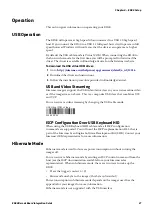
Page 49: ...so you can streamline video as if the imager was a webcam This is a composite USB class that combines UVC and VCP You can activate video streaming by changing the USB cable mode ISCP Configuration Over USB Keyboard HID When using the USB Keyboard HID cable mode all ISCP configuration commands are supported You will need the ISCP implementation DLL that is part of the Intermec Scan Engine Software ...

Page 50: ...Chapter 4 ED40 Setup 38 ED40 Decode Board Integration Guide ...

Page 51: ...es the information needed to create a firmware download application for your ED40 You will find details on Connections for Firmware Download Downloading Firmware Firmware Download Command Set Firmware Download Flow Chart Checksum Calculation RTS CTS Hardware Protocol ACK Software Protocol ...

Page 52: ... page 42 RS 232 Interface Connections for Firmware Download RS 232 Interface Contact Description RS 232 Interface Firmware Download Host Contact Description 1 Vcc Scanner 2 RXD 3 Must Be Connected To Vcc 4 Power Enable 5 TXD 6 RTS 7 GND Scanner 8 Must Be Connected To Vcc 9 LED 10 CTS 11 Buzzer 12 Must Be Connected To Vcc ED40 HOST 1 2 3 4 5 6 7 8 9 10 11 12 RXD Trigger Power enable TXD RTS GND Det...

Page 53: ...d USB Interface Contact Description USB Interface Firmware Download Host Contact Description 1 Vcc Scanner 2 USB D 3 Must be connected to Vcc 4 Power Enable 5 USB D 6 Do not connect 7 GND Scanner 8 Must be connected to GND 9 LED 10 Must be connected to Vcc 11 Buzzer 12 Must Be Connected To Vcc ED40 HOST 1 2 3 4 5 6 7 8 9 10 11 12 USB D Trigger Power enable USB D Do not connect GND Detect in 1 LED ...

Page 54: ... level Trigger line high or not connected At power up low level on power enable the imager detects the high levels on contacts Detect In 0 and Detect In 1 and enters firmware download mode Hardware Initialization in a USB Interface These host hardware conditions are required before power up Detect In 2 and Detect In 0 high level Trigger line high or not connected Detect In 1 low level At power up ...

Page 55: ...l used Dialog Between Host and Imager host initiates baud rate auto detection host sends AUTO_DETECT 0x00 imager detects host baud rate imager replies BAUD_RATE_DETECTED 0x75 imager now ready to receive flash driver Downloading the Flash Driver The flash driver is the tool used to communicate between the imager and the host It combines the different firmware download functions necessary to erase r...

Page 56: ...dy to receive firmware download commands When the imager requests a block it sends the host two bytes BLOCK_RQ and BLOCK_NUM Therefore the UART of the host must be able to receive these two bytes without a handshaking protocol If the host is transmitting data the inter character delay must be less than 200 milliseconds If the delay is too long the imager watchdog will automatically re initialize t...

Page 57: ... support RTS CTS activate the ACK software protocol or the no protocol mode by sending the PROTOCOL_MODE firmware download command For more information see PROTOCOL_MODE 0x10 on page 48 Here are a few important points when sending commands If the host is transmitting data the inter character delay must be less than 200 milliseconds because of the imager watchdog timeout Header bin Firmware Downloa...

Page 58: ...ed the most significant byte must be sent first The firmware file raw or bin is provided by Intermec contact your Intermec representative Do not download the header of a bin firmware file Addresses for reading and writing in flash memory must be even Note There is no error management in the Firmware Download Protocol ...

Page 59: ... 0x11 Checks that the flash driver is able to read from erase or write to the flash memory of the imager REMOVE_DRIVER 0x12 Removes the driver from the imager FIRMWARE_VERSION 0x13 Requests the version of the firmware present in the flash memory ERASE_ALL 0x14 Erases the flash memory of the imager READ_BLOCK 0x15 Reads a block in the flash memory of the imager WRITE_BLOCK 0x16 Writes a block in th...

Page 60: ...l you may experience problems during the download process In this case Intermec recommends using the RTS CTS or ACK protocol modes Flash Driver Response Note This command must be sent if you are using a USB interface virtual COM The USB interface does not support RTS CTS protocol 8 bits 8 bits 8 bits 8 bits 8 bits 8 bits 8 bits 8 bits 8 bits 8 bits 32 bits cmd param 1 param 2 param 3 param 4 param...

Page 61: ...CII string terminated by 0 maximum 50 characters 8 bits 8 bits 8 bits 8 bits 8 bits 8 bits 8 bits 8 bits 8 bits 8 bits 32 bits cmd param 1 param 2 param 3 param 4 param 5 param 6 param 7 param 8 checksum 0x00 0x11 0x00 0x00 0x00 0x00 0x00 0x00 0x00 0x00 calculated Status Response OK CMD_ACK 0x32 Not OK undefined byte error bad checksum or incorrect parameter Example 8 bits 8 bits 8 bits 8 bits 8 b...

Page 62: ...N 0x00 The host must wait 100ms before sending the AUTO DETECTION byte For more information see Baud Rate Auto Detect on page 43 When firmware download is completed After reception of this command the imager resets itself Host Request Flash Driver Response 8 bits 8 bits 8 bits 8 bits 8 bits 8 bits 8 bits 8 bits 8 bits 8 bits 32 bits cmd param 1 param 2 param 3 param 4 param 5 param 6 param 7 param...

Page 63: ...d param 1 param 2 param 3 param 4 param 5 param 6 param 7 param 8 checksum 0x00 0x13 0x00 0x00 0x00 0x00 0x00 0x00 0x00 0x00 calculated Status Response OK CMD_ACK 0x32 Not OK undefined byte error bad checksum or incorrect parameter Note The first 4 reserved bytes and the product ID 4 bytes will always be the same Only the information the follows the product ID field in the firmware version field w...

Page 64: ...e 8 bits 8 bits 8 bits 8 bits 8 bits 8 bits 8 bits 8 bits 8 bits 8 bits 32 bits cmd param 1 param 2 param 3 param 4 param 5 param 6 param 7 param 8 checksum 0x00 0x14 0x00 0x00 0x00 0x00 0x00 0x00 0x00 0x00 calculated Status Response OK CMD_ACK 0x32 Not OK undefined byte error bad checksum or incorrect parameter Note Depending on the type of flash memory installed in the imager erasing the flash m...

Page 65: ...ESS points to bytes and must be compatible with flash memory size Flash Driver Response Flash Driver sends After sending the ACK response the flash driver sends the requested block in the following format 8 bits 8 bits 8 bits 8 bits 8 bits 8 bits 8 bits 8 bits 8 bits 8 bits 32 bits cmd param 1 param 2 param 3 param 4 param 5 param 6 param 7 param 8 checksum 0x00 0x15 BLOCK_SIZE ADDRESS 0x00 0x00 c...

Page 66: ... from the imager the host sends the block using the following format Flash Driver Response 8 bits 8 bits 8 bits 8 bits 8 bits 8 bits 8 bits 8 bits 8 bits 8 bits 32 bits cmd param 1 param 2 param 3 param 4 param 5 param 6 param 7 param 8 checksum 0x00 0x16 BLOCK_SIZE ADDRESS 0x00 0x00 calculated MSB LSB MSB byte 2 byte 3 LSB Status Response OK CMD_ACK 0x32 Not OK undefined byte error bad checksum o...

Page 67: ...imum 256 MSB most significant byte LSB least significant byte ADDRESS points to bytes and must be compatible with flash memory size BYTE to be written in block of flash memory Flash Driver Response 8 bits 8 bits 8 bits 8 bits 8 bits 8 bits 8 bits 8 bits 8 bits 8 bits 32 bits cmd param 1 param 2 param 3 param 4 param 5 param 6 param 7 param 8 checksum 0x00 0x17 BLOCK_SIZE ADDRESS BYTE 0x00 calculat...

Page 68: ...6 Receive block number i Checksum received Checksum calculated Write block in file Curr_Vers i i Flash_Size 256 Yes No Yes No Yes No Close file Curr_Vers Open file New_Vers Calculate File_Size in bytes Send command ERASE_ALL File_Size Flash_Size Yes No i 0 Send command REMOVE_DRIVER i Send command WRITE_BLOCK block_size 256 address i 256 Send the 256 bytes of block i Read the 256 bytes of block i ...

Page 69: ...ksum 0x00 0xBD 0x00 0x380 0x00 0x00 0x130 0x180 0x00 0x00 checksum 0x000006ED CHK BYTEi NBBYTES i i 0 NBBYTES 1 CHK 32bits Checksum Example frame cmd parm 1 parm 2 parm 3 parm 4 parm 5 parm 6 parm 7 parm 8 chk value 0x00 0x15 0x00 0x80 0x00 0x00 0x4C 0x80 0x00 0x00 0x00000 6ED weight 10 9 8 7 6 5 4 3 2 1 value weight 0x00 0xBD 0x00 0x380 0x00 0x00 0x130 0x180 0x00 0x00 ...

Page 70: ...receives permission from the host transmits a byte removes the request after transmission of the byte waits for the host to remove permission before making another request The host grants permission when the imager requests to transmit a byte awaits reception of the byte removes permission after receiving the byte Host Signals Imager Signals Description RXD input TXD output Imager transmits data t...

Page 71: ...st be used by hosts that are not designed to use the RTS CTS hardware protocol The host must send the ACK_MODE command to the imager before any other command to activate the ACK software protocol This deactivates the default RTS CTS hardware protocol When in ACK mode the imager sends a byte then waits for an ACK character 0x06 from the host before sending the next byte This acknowledge tells the i...

Page 72: ...a byte to the imager without using any protocol Transmission from the imager to the host B 1 The imager transmits the first byte B 2 The host transmits the acknowledge ACK 0x06 B 3 The imager transmits the next byte B 4 The host transmits the acknowledge ACK 0x06 ACK 0x06 imager TXD to host RXD ACK 0x06 Host TXD to imager RXD byte byte byte no protocol A B 2 B 1 B 3 B 4 ...

Page 73: ... information EA11 Imager Features EA11 ED40 Views EA11 Reading Distances Operational Current EA11 ED40 Inrush Currents Mechanical Dimensions Imager Ribbon Cable Connecting to ED40 Imager Connector Contact Assignment Note For detailed information on the EA11 imager see the EA11 Imager Integration Guide available from your Intermec OEM representative ...

Page 74: ... compatible with Intermec s family of decoded scan engines EA11 ED40 Views Mounted EA11 on the ED40 Decode Board Unmounted EA11 with the ED40 Decode Board EA11 Reading Distances All distances are measured from the front of a non integrated scan engine using Grade A symbologies and an Intermec decoder Scan rate is 200 frames sec for 1D bar codes and 56 frames sec for 2D bar codes An exit window wil...

Page 75: ...5 cm 2 44 cm 17 2 1 mm 40 mils 8 cm 3 1 83 cm 32 4 UPC EAN 100 0 33 mm 13 mils 5 cm 2 32 cm 12 5 DataMatrix 0 19 mm 7 5 mils 6 3 cm 2 5 17 3 cm 6 7 0 25 mm 10 mils 4 8 cm 1 9 22 cm 8 6 0 38 mm 15 mils 29 cm 11 3 PDF417 0 16 mm 6 6 mils 6 2 cm 2 4 15 4 cm 6 0 25 mm 10 mils 4 5 cm 1 8 23 cm 9 0 38 mm 15 mils 4 cm 1 6 37 cm 14 4 8 4 6 2 0 2 4 in 6 8 10 10 cm 10 5 0 5 10 15 20 20 15 25 25 0 50 40 30 2...

Page 76: ... 1 cm 2 in 40 8 cm 15 9 in UPC EAN 100 0 33 mm 13 mils 5 cm 2 in 30 cm 11 7 in DataMatrix 0 19 mm 7 5 mils 6 5 cm 2 5 in 16 6 cm 6 5 in 0 25 mm 10 mils 5 cm 2 in 21 cm 8 2 in 0 38 mm 15 mils 28 cm 10 9 in PDF417 0 16 mm 6 6 mils 6 3 cm 2 5 in 14 2 cm 5 5 in 0 25 mm 10 mils 4 7 cm 1 8 in 22 cm 8 6 in 0 38 mm 15 mils 5 1 cm 2 in 33 8 cm 13 2 in 8 4 6 2 0 2 4 in 6 8 10 10 cm 10 5 0 5 10 15 20 20 15 2...

Page 77: ...232 Interface USB Interface 3 3 V 5 0 V 3 3 V 5 0 V Full operational power enable low trigger low Typical default parameters 455 mA 275 mA 475 mA 285 mA Maximum aimer always on full lighting 630 mA 375 mA 650 mA 385 mA Active Idle power enable low trigger high 65 mA max 50 mA max 100 mA max 70 mA max Hibernate current power enable low trigger high hibernate mode on 4 mA 3 mA N A N A Imager off pow...

Page 78: ...board The information is divided in to 2 sections depending on the interface used RS 232 cable USB cable Using an RS 232 Cable Power Up with Vcc Inrush Current EA11 ED40 Power Up with Vcc Inrush Current RS 232 Power enable and trigger low Note Inrush currents vary depending on many parameters The graphs in this section are measurements used to indicate approximate values ...

Page 79: ...r Up with Power Enable Inrush Current EA11 ED40 Power Up with power enable Inrush Current RS 232 Power enable switched from high to low Power Up Vcc Inrush Current to Active Idle EA11 ED40 Power Up Vcc Inrush Current to Active Idle RS 232 Power enable low trigger high ...

Page 80: ...D40 Decode Board Integration Guide Active Idle to Scan Inrush Current EA11 ED40 Active Idle to Scan Inrush Current RS 232 Trigger pulled low or trigger pressed to initiate a scan Scanning Current EA11 ED40 Scanning Current RS 232 ...

Page 81: ...er ED40 Decode Board Integration Guide 69 Hibernate Current EA11 ED40 Hibernate Current RS 232 Using a USB Cable Power Up with Vcc Inrush Current EA11 ED40 Power Up with Vcc Inrush Current USB Power enable and trigger low ...

Page 82: ... Current 1 EA11 ED40 Power Up with power enable Inrush Current 1 Power enable switched from high to low Power Up with Power Enable Inrush Current 2 Zoom EA11 ED40 Power Up with power enable Inrush Current 2 Zoom USB Power enable switched from high to low This is a zoom in on the previous graphic ...

Page 83: ...er Up Vcc Inrush Current to Active Idle EA11 ED40 Power Up Vcc Inrush Current to Active Idle USB Power enable low trigger high Active Idle to Scan Inrush Current EA11 ED40 Active Idle to Scan Inrush Current USB Trigger pulled low or trigger pressed to initiate a scan ...

Page 84: ...Appendix A EA11 Imager 72 ED40 Decode Board Integration Guide Scanning Current EA11 ED40 Scanning Current USB ...

Page 85: ...ed on the ED40 Decode Board Tolerances 0 20 mm 0 008 in 19 5 mm 0 77 in 34 mm 1 34 in Positioning holes 2 places Mounting holes 2 places M1 6 screws 2 to mount the PCB to bracket max torque 19 Ncm 1 68 lb in 1 Ncm 0 09 lb in 22 8 mm 0 90 in 20 5 mm 0 81 in Imager Position 1 Imager Position 2 Note There are two positions for mounting the imager See Mounted Imager Position on page 75 for details ...

Page 86: ...0 into your design EA11 ED40 Mounting and Positioning Holes Positioning holes 2 places diameter 2 mm 0 08 in depth 2 5 mm 0 10 in Hole for M2 screw 2 places min engagement 4 mm 0 16 in 30 mm 1 18 in 7 7 mm 0 30 in 12 7 mm 0 50 in Note The EA11 can also be used unmounted with the ED40 decode board The ribbon cable should be 50 8 cm 2 in in length with a maximum of 10 16 cm 4 in See Imager Ribbon Ca...

Page 87: ...ager to your design if necessary This can be helpful if you have one design and would like the possibility of using any of the Intermec imagers supported by the ED40 decode board in your design EA11 Imager Position on the Mounting Bracket 20 5 mm 0 81 in 22 8 mm 0 90 in Imager position 1 Imager position 2 Imager Position 1 Imager Position 2 Screws 2 to mount imager to bracket PT screw K18 max torq...

Page 88: ... the orientation of this cable is not symmetrical The shield is tied to PIN1 which makes the cable orientation important the text DB1 is printed on the end of the cable that goes to the decode board The other end goes to the imager 0 660 cm 0 005 0 260 in 0 002 2X 4X 0 762 cm 0 300 in 4X 0 635 cm 0 250 in 2X 0 127 cm 0 050 in 4X R 0 020 cm 0 010 0 008 in 0 004 5 080 cm 2 000 in 0 635 cm 0 250 in 0...

Page 89: ...r cover Use the tip of your finger to open the cover in the direction shown Be careful not to force open the cover or open it more than 80 or it will break 2 Pull gently on the ribbon cable along the axis of the cable and remove the ribbon cable 3 Connect a new ribbon cable to the imager connector Make sure that the contacts are facing the board The connectors are very fragile Open and close the c...

Page 90: ...off aiming beam off laser framing or aiming beam depends on the imager 7 light_ctrl output 0 Lighting off 1 Lighting on or pulse width modulation 10KHz 100KHz Controls the intensity of the lighting LEDs 8 power enable output Sensor enable control 1 Enabled 0 Power down Only shuts down the sensor does not turn off the LEDs The imager setup is kept 9 SDA input output Serial bus data 10 SCL output Se...

Page 91: ...ger ED40 Decode Board Integration Guide 79 20 data in intput Data input bit 7 21 pixel clock intput Pixel clock input for data in Contact Assignment EA11 Imager Connector Contact Name I O Description Electrical Equivalent ...

Page 92: ...Appendix A EA11 Imager 80 ED40 Decode Board Integration Guide ...

Page 93: ...llowing information EA20X Imager Features EA20X ED40 Views Operational Current EA20X ED40 Inrush Currents Mechanical Dimensions Imager Ribbon Cable Connecting to ED40 Imager Connector Contact Assignment Note For detailed information on the EA20X imager see the EA20X Imager Integration Guide available from your Intermec OEM representative ...

Page 94: ...nge 2D imager Best in class scan rate 60 frames s Reads any 2D symbologies omnidirectionally Highly visible laser framing Highly durable design Fully compatible with Intermec s family of decoded scan engines EA20X ED40 Views Mounted EA20X on the ED40 Decode Board Unmounted EA20X with the ED40 Decode Board ...

Page 95: ...ils 15 5 cm 6 1 in 23 cm 9 1 in 0 2 mm 8 mils 11 5 cm 4 5 in 32 5 cm 12 8 in 0 25 mm 10 mils 8 cm 3 1 in 42 cm 16 5 in 0 5 mm 20 mils 8 cm 3 1 in 80 cm 31 5 in 1 mm 40 mils 13 cm 5 1 in 125 cm 49 2 in UPC EAN 100 0 33 mm 13 mils 7 cm 2 8 in 50 cm 20 in DataMatrix 0 18 mm 7 mils 16 5 cm 6 5 in 20 5 cm 8 1 in 0 25 mm 10 mils 12 5 cm 5 in 32 5 cm 12 8 in 0 38 mm 15 mils 8 cm 3 1 in 50 cm 19 7 in PDF4...

Page 96: ... in 67 cm 26 4 in 1 mm 40 mils 15 cm 6 in 85 cm 33 5 in UPC EAN 100 0 33 mm 13 mils 9 cm 3 5 in 45 cm 17 7 in DataMatrix 0 18 mm 7 mils 17 cm 6 7 in 19 5 cm 7 7 in 0 25 mm 10 mils 15 cm 6 in 29 cm 11 4 in 0 38 mm 15 mils 10 cm 3 9 in 43 cm 17 0 in PDF417 0 17 mm 6 6 mils 15 cm 6 in 22 cm 8 7 in 0 25 mm 10 mils 10 cm 3 9 in 33 cm 13 in 0 38 mm 15 mils 11 cm 4 3 in 48 cm 18 9 in 8 4 6 2 0 2 4 6 8 10...

Page 97: ...32 Interface USB Interface 3 3 V 5 0 V 3 3 V 5 0 V Full Operational power enable low trigger low Typical default parameters 410 mA 255 mA 430 mA 265 mA Maximum aimer always on full lighting 500 mA 300 mA 510 mA 310 mA Active Idle power enable low trigger high 65 mA max 45 mA max 100 mA max 65 mA max Hibernate current power enable low trigger high hibernate activated 1 5 mA 1 2 mA N A N A Imager of...

Page 98: ... board The information is divided in to 2 sections depending on the interface used RS 232 cable USB cable Using an RS 232 Cable Power Up with Vcc Inrush Current EA20X ED40 Power Up with Vcc Inrush Current RS 232 Power enable and trigger low Note Inrush currents vary depending on many parameters The graphs in this section are measurements used to indicate approximate values ...

Page 99: ... Up with Power Enable Inrush Current EA20X ED40 Power Up with power enable Inrush Current RS 232 Power enable switched from high to low Power Up Vcc Inrush Current to Active Idle EA20X ED40 Power Up Vcc Inrush Current to Active Idle RS 232 Power enable low trigger high ...

Page 100: ...40 Decode Board Integration Guide Active Idle to Scan Inrush Current EA20X ED40 Active Idle to Scan Inrush Current RS 232 Trigger pulled low or trigger pressed to initiate a scan Scanning Current EA20X ED40 Scanning Current RS 232 ...

Page 101: ...er ED40 Decode Board Integration Guide 89 Hibernate Current EA20C ED40 Hibernate Current RS 232 Using a USB Cable Power Up with Vcc Inrush Current EA20X ED40 Power Up with Vcc Inrush Current USB Power enable and trigger low ...

Page 102: ...urrent 1 EA20X ED40 Power Up with power enable Inrush Current 1 USB Power enable switched from high to low Power Up with Power Enable Inrush Current 2 Zoom EA20X ED40 Power Up with power enable Inrush Current 2 Zoom USB Power enable switched from high to low This is a zoom in on the previous graphic ...

Page 103: ...r Up Vcc Inrush Current to Active Idle EA20X ED40 Power Up Vcc Inrush Current to Active Idle USB Power enable low trigger high Active Idle to Scan Inrush Current EA20X ED40 Active Idle to Scan Inrush Current USB Trigger pulled low or trigger pressed to initiate a scan ...

Page 104: ...Appendix B EA20X Imager 92 ED40 Decode Board Integration Guide Scanning Current EA20X ED40 Scanning Current USB ...

Page 105: ...in 23 05 mm 0 91 in M1 6 screws 2 to mount the PCB to bracket max torque 19 Ncm 1 68 lb in 1 Ncm 0 09 lb in Imager Position 1 Positioning holes 2 places Mounting holes 2 places 19 5 mm 0 77 in 34 mm 1 34 in 23 05 mm 0 91 in M1 6 screws 2 to mount the PCB to bracket max torque 19 Ncm 1 68 lb in 1 Ncm 0 09 lb in Imager Position 1 Note As opposed to the other imagers there is only one position for mo...

Page 106: ... into your design EA20X ED40 Mounting and Positioning Holes Positioning holes 2 places diameter 2 mm 0 08 in depth 2 5 mm 0 10 in Hole for M2 screw 2 places min engagement 4 mm 0 16 in 30 mm 1 18 in 7 95 mm 0 31 in 12 95 mm 0 51 in Note The EA20X can also be used unmounted with the ED40 decode board The ribbon cable should be 50 8 cm 2 in in length with a maximum of 10 16 cm 4 in See Imager Ribbon...

Page 107: ... the orientation of this cable is not symmetrical The shield is tied to PIN1 which makes the cable orientation important the text DB1 is printed on the end of the cable that goes to the decode board The other end goes to the imager 0 660 cm 0 005 0 260 in 0 002 2X 4X 0 762 cm 0 300 in 4X 0 635 cm 0 250 in 2X 0 127 cm 0 050 in 4X R 0 020 cm 0 010 0 008 in 0 004 5 080 cm 2 000 in 0 635 cm 0 250 in 0...

Page 108: ...or cover Use the tip of your finger to open the cover in the direction shown Be careful not to force open the cover or open it more than 80 or it will break 2 Pull gently on the ribbon cable along the axis of the cable and remove the ribbon cable 3 Connect a new ribbon cable to the imager connector Make sure that the contacts are facing the board The connectors are very fragile Open and close the ...

Page 109: ...ming off aiming beam off laser framing or aiming beam depends on the imager 7 light_ctrl output 0 Lighting off 1 Lighting on or pulse width modulation 10KHz 100KHz Controls the intensity of the lighting LEDs 8 power enable output Sensor enable control 1 Enabled 0 Power down Only shuts down the sensor does not turn off the LEDs The imager setup is kept 9 SDA input output Serial bus data 10 SCL outp...

Page 110: ...ager 98 ED40 Decode Board Integration Guide 20 data in input Data input bit 7 21 pixel clock input Pixel clock input for data in Contact Assignment EA20X Imager Connector Contact Name I O Description Electrical Equivalent ...

Page 111: ...following information EA21 Imager Features EA21 ED40 Views EA21 Reading Distances Operational Current Operational Current Mechanical Dimension Imager Ribbon Cable Connecting to ED40 Imager Connector Contact Assignment Note For detailed information on the EA21 imager see the EA21 Imager Integration Guide available from your Intermec OEM representative ...

Page 112: ...eading widest in the industry Omnidirectional scanning of 1D and 2D bar codes Laser framing for fast intuitive operation Document imaging Fully compatible with Intermec s family of decoded scan engines EA21 ED40 Views Mounted EA21 on the ED40 Decode Board Unmounted EA21 with the ED40 Decode Board ...

Page 113: ... 39 0 15 6 mils 12 cm 4 72 in 18 cm 7 09 in 0 25 mm 10 mils 5 cm 1 97 in 30 cm 11 81 in 0 5 mm 20 mils 5 cm 1 97 in 60 cm 23 62 in 1 mm 40 mils 9 cm 3 54 in 95 cm 37 40 in UPC EAN 100 0 33 mm 13 mils 5 cm 1 97 in 41 cm 16 14 in DataMatrix 0 25 mm 10 mils 12 cm 4 72 in 22 cm 8 66 in 0 38 mm 15 mils 8 cm 3 15 in 35 cm 13 78 in PDF417 0 25 mm 10 mils 7 cm 2 75 in 29 cm 11 42 in 0 38 mm 15 mils 7 cm 2...

Page 114: ... 65 in 1 mm 40 mils 9 cm 3 54 in 75 cm 29 53 in UPC EAN 100 0 33 mm 13 mils 5 cm 1 97 in 38 cm 14 96 in DataMatrix 0 25 mm 10 mils 12 cm 4 72 in 22 cm 8 66 in 0 38 mm 15 mils 8 cm 3 15 in 34 cm 13 39 in PDF417 0 25 mm 10 mils 7 cm 2 75 in 28 cm 11 02 in 0 38 mm 15 mils 7 cm 2 75 in 40 cm 15 75 in 0 4 8 0 10 20 cm PDF417 10 mils 0 15mm 6 mils 0 25 mm 10 mils 0 5 mm 20 mils Data Matrix 10 mils in 0 ...

Page 115: ...terface USB Interface 3 3 V 5 0 V 3 3 V 5 0 V Full operational power enable low trigger low Typical default parameters 400 mA 250 mA 425 mA 260 mA Maximum aimer always on full lighting 500 mA 290 mA 510 mA 300 mA Active Idle current power enable low trigger high 65 mA max 45 mA max 100 mA max 65 mA max Hibernate current power enable low trigger high hibernate activated 1 5 mA 1 2 mA N A N A Imager...

Page 116: ...board The information is divided in to 2 sections depending on the interface used RS 232 cable USB cable Using an RS 232 Cable Power Up with Vcc Inrush Current EA21 ED40 Power Up with Vcc Inrush Current RS 232 Power enable and trigger low Note Inrush currents vary depending on many parameters The graphs in this section are measurements used to indicate approximate values ...

Page 117: ...r Up with Power Enable Inrush Current EA21 ED40 Power Up with power enable Inrush Current RS 232 Power enable switched from high to low Power Up Vcc Inrush Current to Active Idle EA21 ED40 Power Up Vcc Inrush Current to Active Idle RS 232 Power enable low trigger high ...

Page 118: ...D40 Decode Board Integration Guide Active Idle to Scan Inrush Current EA21 ED40 Active Idle to Scan Inrush Current RS 232 Trigger pulled low or trigger pressed to initiate a scan Scanning Current EA21 ED40 Scanning Current RS 232 ...

Page 119: ...r ED40 Decode Board Integration Guide 107 Hibernate Current EA21 ED40 Hibernate Current 5RS 232 Using a USB Cable Power Up with Vcc Inrush Current EA21 ED40 Power Up with Vcc Inrush Current USB Power enable and trigger low ...

Page 120: ...h Current 1 EA21 ED40 Power Up with power enable Inrush Current 1 Power enable switched from high to low Power Up with Power Enable Inrush Current 2 Zoom EA21 ED40 Power Up with power enable Inrush Current 2 Zoom USB Power enable switched from high to low This is a zoom in on the previous graphic ...

Page 121: ...er Up Vcc Inrush Current to Active Idle EA21 ED40 Power Up Vcc Inrush Current to Active Idle USB Power enable low trigger high Active Idle to Scan Inrush Current EA21 ED40 Active Idle to Scan Inrush Current USB Trigger pulled low or trigger pressed to initiate a scan ...

Page 122: ...Appendix C EA21 Imager 110 ED40 Decode Board Integration Guide Scanning Current EA21 ED40 Scanning Current USB ...

Page 123: ...ed on the ED40 Decode Board Tolerances 0 20 mm 0 008 in Positioning holes 2 places Mounting holes 2 places 19 5 mm 0 77 in 34 mm 1 34 in 19 9 mm 0 78 in M1 6 screws 2 to mount the PCB to bracket max torque 19 Ncm 1 68 lb in 1 Ncm 0 09 lb in 22 2 mm 0 87 in Imager Position 1 Imager Position 2 Note There are two positions for mounting the imager See Mounted Imager Position on page 113 for details ...

Page 124: ...0 into your design EA21 ED40 Mounting and Positioning Holes Positioning holes 2 places diameter 2 mm 0 08 in depth 2 5 mm 0 10 in Hole for M2 screw 2 places min engagement 4 mm 0 16 in 30 mm 1 18 in 7 1 mm 0 28 in 12 1 mm 0 48 in Note The EA21 can also be used unmounted with the ED40 decode board The ribbon cable should be 50 8 cm 2 in in length with a maximum of 10 16 cm 4 in See Imager Ribbon Ca...

Page 125: ...ager to your design if necessary This can be helpful if you have one design and would like the possibility of using any of the Intermec imagers supported by the ED40 decode board in your design EA21 Imager Position on the Mounting Bracket 19 9 mm 0 78 in 22 2 mm 0 87 in Imager position 1 Imager position 2 Imager Position 1 Imager Position 2 Screws 2 to mount imager to bracket PT screw K18 max torq...

Page 126: ... the orientation of this cable is not symmetrical The shield is tied to PIN1 which makes the cable orientation important the text DB1 is printed on the end of the cable that goes to the decode board The other end goes to the imager 0 660 cm 0 005 0 260 in 0 002 2X 4X 0 762 cm 0 300 in 4X 0 635 cm 0 250 in 2X 0 127 cm 0 050 in 4X R 0 020 cm 0 010 0 008 in 0 004 5 080 cm 2 000 in 0 635 cm 0 250 in 0...

Page 127: ...or cover Use the tip of your finger to open the cover in the direction shown Be careful not to force open the cover or open it more than 80 or it will break 2 Pull gently on the ribbon cable along the axis of the cable and remove the ribbon cable 3 Connect a new ribbon cable to the imager connector Make sure that the contacts are facing the board The connectors are very fragile Open and close the ...

Page 128: ...ing off aiming beam off laser framing or aiming beam depends on the imager 7 light_ctrl output 0 Lighting off 1 Lighting on or pulse width modulation 10KHz 100KHz Controls the intensity of the lighting LEDs 8 power enable output Sensor enable control 1 Enabled 0 Power down Only shuts down the sensor does not turn off the LEDs The imager setup is kept 9 SDA input output Serial bus data 10 SCL outpu...

Page 129: ...ger ED40 Decode Board Integration Guide 117 20 data in input Data input bit 7 21 pixel clock input Pixel clock input for data in Contact Assignment EA21 Imager Connector Contact Name I O Description Electrical Equivalent ...

Page 130: ...Appendix C EA21 Imager 118 ED40 Decode Board Integration Guide ...

Page 131: ...e following information EA30 Imager Features EA30 ED40 Views EA30 Reading Distances Operational Current EA30 ED40 Inrush Currents Motion Tolerance Mechanical Dimension Imager Ribbon Cable Connecting to ED40 Imager Connector Contact Assignment Note For detailed information on the EA30 imager see the EA30 Imager Integration Guide available from your Intermec OEM representative ...

Page 132: ...Features Highest motion tolerance on the market Reads colored bar codes Laser framing for easy aiming EA30 ED40 Views Mounted EA30 on the ED40 Decode Board Unmounted EA30 with the ED40 Decode Board Note For more information on motion tolerance see Motion Tolerance on page 131 ...

Page 133: ... cm 3 74 in 11 5 cm 4 53 in 0 125 mm 5 mils 8 cm 3 15 in 14 5 cm 5 71 in 0 5 mm 20 mils 6 5 cm 2 56 in 50 cm 19 69 in 1 mm 40 mils 9 5 cm 3 74 in 75 cm 29 53 in EAN UPC 100 0 33 mm 13 mils 6 cm 2 36 in 34 cm 13 39 in DataMatrix 0 18 mm 7 mils 7 5 cm 2 95 in 16 5 cm 6 5 in 0 25 mm 10 mils 6 cm 2 36 in 23 cm 9 06 in 0 38 mm 15 mils 5 5 cm 2 17 in 34 5 cm 13 58 in PDF417 0 25 mm 10 mils 5 5 cm 2 17 i...

Page 134: ...1 mm 40 mils 9 5 cm 3 74 in 62 cm 24 41 in EAN UPC 100 0 33 mm 13 mils 6 cm 2 36 in 31 5 cm 12 4 in DataMatrix 0 18 mm 7 mils 8 cm 3 15 in 15 5 cm 6 1 in 0 25 mm 10 mils 6 5 cm 2 56 in 21 5 cm 8 46 in 0 38 mm 15 mils 5 5 cm 2 17 in 31 5 cm 12 4 in PDF417 0 25 mm 10 mils 5 5 cm 2 17 in 25 cm 9 84 in 0 38 mm 15 mils 7 cm 2 76 in 34 cm 13 39 in cm PDF417 10 mils 0 5 mm 20 mils 1 mm 40 mils Data Matri...

Page 135: ...ager Connector Contact Assignment on page 139 The peak current for contacts 20 21 and 22 depend on the illumination level selected For an idea of peak current see on page 132 Operational Current ED40 Decode Board EA30 contact 10 Specification RS 232 Interface USB Interface 3 3 V 5 0 V 3 3 V 5 0 V Full operational power enable low trigger low Maximum aimer always on 300 mA 190 mA 320 mA 200 mA Acti...

Page 136: ...board The information is divided in to 2 sections depending on the interface used RS 232 cable USB cable Using an RS 232 Cable Power Up with Vcc Inrush Current EA30 ED40 Power Up with Vcc Inrush Current RS 232 Power enable and trigger low Note Inrush currents vary depending on many parameters The graphs in this section are measurements used to indicate approximate values ...

Page 137: ...r Up with Power Enable Inrush Current EA30 ED40 Power Up with power enable Inrush Current RS 232 Power enable switched from high to low Power Up Vcc Inrush Current to Active Idle EA30 ED40 Power Up Vcc Inrush Current to Active Idle RS 232 Power enable low trigger high ...

Page 138: ...D40 Decode Board Integration Guide Active Idle to Scan Inrush Current EA30 ED40 Active Idle to Scan Inrush Current RS 232 Trigger pulled low or trigger pressed to initiate a scan Scanning Current EA30 ED40 Scanning Current RS 232 ...

Page 139: ...r ED40 Decode Board Integration Guide 127 Hibernate Current EA30 ED40 Hibernate Current 5RS 232 Using a USB Cable Power Up with Vcc Inrush Current EA30 ED40 Power Up with Vcc Inrush Current USB Power enable and trigger low ...

Page 140: ...h Current 1 EA30 ED40 Power Up with power enable Inrush Current 1 Power enable switched from high to low Power Up with Power Enable Inrush Current 2 Zoom EA30 ED40 Power Up with power enable Inrush Current 2 Zoom USB Power enable switched from high to low This is a zoom in on the previous graphic ...

Page 141: ...er Up Vcc Inrush Current to Active Idle EA30 ED40 Power Up Vcc Inrush Current to Active Idle USB Power enable low trigger high Active Idle to Scan Inrush Current EA30 ED40 Active Idle to Scan Inrush Current USB Trigger pulled low or trigger pressed to initiate a scan ...

Page 142: ...Appendix D EA30 Imager 130 ED40 Decode Board Integration Guide Scanning Current EA30 ED40 Scanning Current USB ...

Page 143: ...n and the environment Note Setting up the imager for maximum motion tolerance will modify some imager performances such as reading distances and peak current This section gives an idea of how different performances are affected Motion Tolerance Modes Mode Settings Motion Tolerance Lighting Peak Current Imager Performance Standard default Illumination level 60 Lighting goal 128 190 in sec 500 mA No...

Page 144: ...urrent is 1200 mA when using full illumination see Motion Tolerance Table The length of time the peak current lasts depends on the exposure time For more details on peak current with maximum exposure time see the EA30 Integration Guide Peak Current Diagram For contacts 20 21 and 22 Peak level Exposure time Frame time Note Frame time 1 Frame rate depending on the image size ...

Page 145: ...ed on the ED40 Decode Board Tolerances 0 20 mm 0 008 in Positioning holes 2 places Mounting holes 2 places 19 5 mm 0 77 in 34 mm 1 34 in M1 6 screws 2 to mount the PCB to bracket max torque 19 Ncm 1 68 lb in 1 Ncm 0 09 lb in 20 9 mm 0 82 in 23 2 mm 0 91 in Imager Position 1 Imager Position 2 Note There are two positions for mounting the imager See Mounted Imager Position on page 135 for details ...

Page 146: ... of 4 mm 0 16 in to mount the imager ED40 into your design EA30 ED40 Mounting and Positioning Holes Positioning holes 2 places diameter 2 mm 0 08 in depth 2 5 mm 0 10 in Hole for M2 screw 2 places min engagement 4 mm 0 16 in 30 mm 1 18 in 7 95 mm 0 31 in 12 95 mm 0 51 in Note The EA30 can also be used unmounted with the ED40 decode board See Imager Ribbon Cable Connecting to ED40 on page 136 for m...

Page 147: ...ager to your design if necessary This can be helpful if you have one design and would like the possibility of using any of the Intermec imagers supported by the ED40 decode board in your design EA30 Imager Position on the Mounting Bracket 20 9 mm 0 82 in 23 2 mm 0 91 in Imager Position 2 Imager Position 1 Imager position 1 Imager position 2 Screws 2 to mount imager to bracket PT screw K18 max torq...

Page 148: ...r the imager s illumination LEDs Intermec recommends using a shielded flex cable to contain emission from high speed clock signals in this cable EA30 Y Ribbon Cable for Connection to ED40 Decode Board and Host 1 2 3 4 5 6 1 2 3 4 5 6 7 8 9 10 11 12 13 14 15 16 17 19 1 2 3 4 5 6 7 8 9 10 11 12 13 14 15 16 17 19 20 21 22 23 24 25 18 20 21 18 Bottom view Top view Connects to host 6 contacts on bottom...

Page 149: ...end of the ribbon cable is connected to the tin plated Molex connector P N 54393 2182 on the ED40 Decode Board 6 Pin End Connected to the Host The 6 contact end of the ribbon cable is connected to the host example connector Molex 52559 0652 This connection provides the extra power needed for the EA30 imager ...

Page 150: ...long the axis of the cable and remove the ribbon cable 3 Connect a new ribbon cable to the imager connector Make sure that the contacts are facing the board 1 45 0 1 1 05 0 1 0 3 0 07 0 85 0 1 0 25 0 1 0 3 0 02 0 3 0 07 0 6 0 02 0 6 0 02 B 0 03 A 0 03 B 0 6 0 05 2 R0 2 MAX 3 2 0 3 0 3 0 3 1 25 Effective stacking length 0 65 T 0 12 0 03 0 04 0 03 0 04 0 03 Effective stacking length Reinforcement bo...

Page 151: ...ly shuts down the sensor does not turn off the LEDs The imager setup is kept 8 SDA Input output Serial bus data Use the serial bus interface to program the imager registers This line is pulled up to Vin_sensor by a 1 5kOhm resistor 9 SCL Input output Serial bus clock Use the serial bus interface to program the imager registers This line is pulled up to Vin_sensor by a 1 5kOhm resistor 10 Vin_senso...

Page 152: ...ntegration Guide 20 Vin_lighting Lighting power supply 3 3 5 V 21 Vin_lighting Lighting power supply 3 3 5 V 22 Vin_lighting Lighting power supply 3 3 5 V 23 GND Ground 24 GND Ground 25 GND Ground Contact Name I O Description Electrical Equivalent ...

Page 153: ...Appendix D EA30 Imager ED40 Decode Board Integration Guide 141 ...

Page 154: ......

Page 155: ... 36th Avenue West Everett Washington 98203 U S A tel 425 348 2600 fax 425 355 9551 www intermec com 2010 Intermec Technologies Corporation All rights reserved ED40 Decode Board Integration Guide 3 242049 00 P N 3 242049 00 Rev B ...

Reviews: