Chapter 4 — ED40 Setup
ED40 Decode Board Integration Guide
31
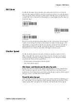
AEC Zone
By default the imager uses automatic exposure control (AEC) to control and
calculate the amount of light to reach the sensor to produce an acceptable image.
This can also be called automatic shutter speed. The AEC Zone setting allows you
to apply AEC only to the center of the imager, to an area bigger than the center, or
the whole image.
How you use this setting depends on where the bar code is located. For example,
use the center setting if your bar code is always in centered in the imager’s view
(hand held scanning or bar code always in the same location). That way AEC is
only applied to where it is needed - and will not take in to consideration the
bright areas around the bar code when adjusting the shutter speed.
Shutter Speed
By default shutter speed is automatic (automatic exposure control or AEC).
When using AEC, the shutter speed will vary between the lowest and highest
shutter speeds possible for your imager. However you can change the shutter
speed settings. There are two possibilities:
•
Set minimum and maximum shutter speeds.
•
Set a fixed shutter speed.
Minimum and Maximum Shutter Speeds
Setting minimum and maximum shutter speeds allows you to set limits for the
AEC (automatic exposure control). This can be useful in certain fixed mount
applications. For information on optimizing your imager using the shutter speed
settings, contact your Intermec System Engineer.
Fixed Shutter Speed
A fixed shutter speed can be useful in a specific environment where lighting and
bar code quality are very consistent. When the fixed shutter speed is set to 0, the
imager applies AEC and applies the minimum and maximum shutter speeds.
Small (center only)
SW 7B 4B 00
Medium (*)
SW 7B 4B 01
Large (full image)
SW 7B 4B 02
Summary of Contents for ED40
Page 4: ...iv ED40 Decode Board Integration Guide ...
Page 22: ...Chapter 2 Mechanical Integration 10 ED40 Decode Board Integration Guide ...
Page 32: ...Chapter 3 Electrical Integration 20 ED40 Decode Board Integration Guide ...
Page 48: ...Chapter 4 ED40 Setup 36 ED40 Decode Board Integration Guide UPC A ...
Page 50: ...Chapter 4 ED40 Setup 38 ED40 Decode Board Integration Guide ...
Page 92: ...Appendix A EA11 Imager 80 ED40 Decode Board Integration Guide ...
Page 130: ...Appendix C EA21 Imager 118 ED40 Decode Board Integration Guide ...
Page 153: ...Appendix D EA30 Imager ED40 Decode Board Integration Guide 141 ...
Page 154: ......

