background image


IF5 Fixed Reader Quick Start Guide 

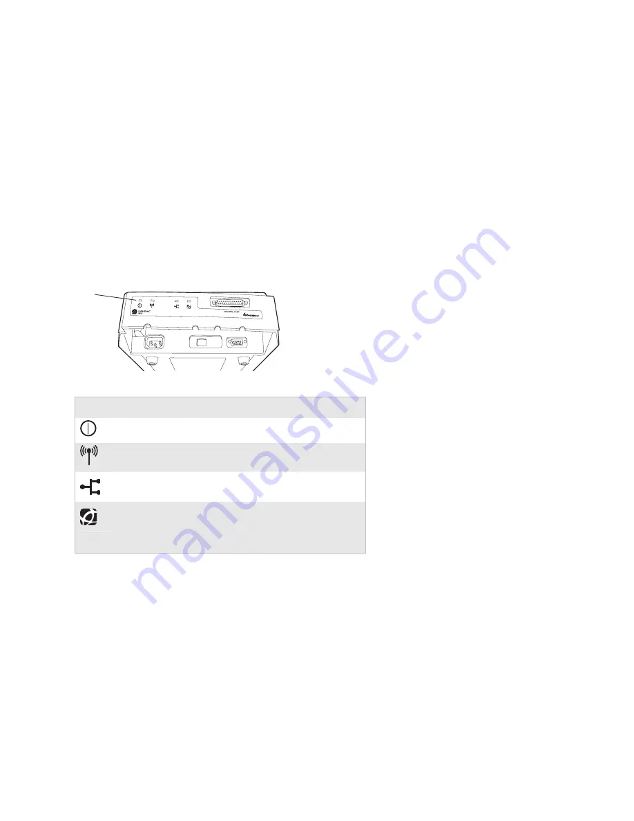
Understanding the LEDs 

The front panel of the IF5 includes four LEDs that indicate 
status. 

LE

D

s


LED Descriptions 

Icon 

LED Name 

Description 


Power 

Remains on after the IF5 boots. 


Wireless 
communication 

Flashes when a frame is transmitted or 
received on the 802.11g radio port. 


Wired LAN 

Flashes when a frame is transmitted or 
received on the Ethernet port. 


Intermec 
Ready-to-
Work™ 
indicator 

Blue LED remains on when an 
application has connected to the IF5. 
The LED flashes when no applications 
are connected. 

Summary of Contents for IF5

Page 1: ...IF5 Fixed Reader Quick Start Guide ...

Page 2: ...d ArciTech Beverage Routebook CrossBar dcBrowser Duratherm EasyADC EasyCoder EasySet Fingerprint i gistics INCA under license Intellitag Intellitag Gen2 JANUS LabelShop MobileLAN Picolink Ready to Work RoutePower Sabre ScanPlus ShopScan Smart Mobile Computing SmartSystems TE 2000 Trakker Antares and Vista Powered are either trademarks or registered trademarks of Intermec Technologies Corporation T...

Page 3: ...6 What You Need 6 Learning About the IF5 7 Understanding the Front Panel Ports 7 Understanding the Rear Panel Ports 8 Understanding the LEDs 9 Configuring the IF5 10 Connecting the IF5 12 Using a Web Browser Interface 13 Where to Go From Here 14 Specifications 15 Patent Information 15 ...

Page 4: ...iv IF5 Fixed Reader Quick Start Guide ...

Page 5: ...less network This quick start guide explains the IF5 ports and LEDs and how to connect the IF5 to your network IF5 Fixed Reader The IF5 Fixed Reader uses an EPCglobal Gen 2 certified IM5 Module 86x MHz RFID frequency band The IF5 Fixed Reader uses an EPCglobal Gen 2 certified IM5 Module 915 MHz RFID frequency band IF5 Fixed Readers with an IEEE 802 11g radio installed are certified for interoperab...

Page 6: ...u need these items Appropriate AC power cord Appropriate RFID antennas and cables Ethernet cable for an Ethernet network Appropriate radio antennas for the 802 11g radio For more information on power cords antennas cables or other accessories contact your local Intermec representative Government regulatory agencies require that this RFID reader only use approved antennas Therefore this reader uses...

Page 7: ...el and rear panel ports and the LEDs Understanding the Front Panel Ports To access the AC power Ethernet and serial ports unscrew the two thumbscrews on the underside of the cable access door to remove the door Cable access door AC power port Ethernet port Serial port Control port IF5 Front Panel ...

Page 8: ...ion or maintenance Control General purpose input output GPIO interface Use a standard DB25 cable P N 236 057 001 to connect the IF5 to the GPIO Terminal Block accessory Understanding the Rear Panel Ports The IF5 ships with terminators installed on RFID antenna ports 2 3 and 4 Do not remove the terminator from any port unless you are installing an antenna on that port RFID antenna ports 4 places 80...

Page 9: ...ription Power Remains on after the IF5 boots Wireless communication Flashes when a frame is transmitted or received on the 802 11g radio port Wired LAN Flashes when a frame is transmitted or received on the Ethernet port Intermec Ready to Work indicator Blue LED remains on when an application has connected to the IF5 The LED flashes when no applications are connected ...

Page 10: ...less network connection you need to connect to a secure network you are not using a DHCP server For help with assigning a static IP address configuring the IF5 for a secure network or if you are not using a DHCP server see the IF5 Fixed Reader User s Manual P N 074747 To configure the IF5 for a DHCP enabled wireless network 1 Connect a null modem cable to the IF5 serial port and to your desktop PC...

Page 11: ...uration menu appears 7 Press the down arrow key to select 802 11g Radio and then press Enter The 802 11g Radio settings list appears with Node Type set to Disabled 8 Press Enter and then press the up arrow key to select Enabled 9 Press Enter The 802 11g Radio settings list appears 10 Press the down arrow key to select SSID Network Name and then press Enter An entry field appears ...

Page 12: ...Connecting the IF5 Connecting the IF5 After you have made any necessary configuration settings you can connect the IF5 to your network To connect the IF5 to your network 1 Attach at least one and up to four RFID antennas to the RFID antenna ports starting with port 1 Do not remove the terminators from unused antenna ports Each port must have an antenna or a terminator connected Do not apply power ...

Page 13: ...llustration shows how to mount the IF5 vertically or horizontally 6 For an Ethernet network connect the Ethernet cable to your network For a wireless network continue with the next step 7 Connect the IF5 s AC power cord to an AC outlet As soon as you apply power the IF5 boots and the green Power LED turns on After the IF5 boots it is ready to communicate in your network To verify the connection yo...

Page 14: ...pears 3 Enter your username and password in the entry fields The default for each is intermec 4 Click Login The Ethernet screen appears You can view and configure many IF5 settings from the configuration web pages For more information see the IF5 user s manual Where to Go From Here For more information on configuring and maintaining the IF5 see the IF5 Fixed Reader User s Manual P N 074747 ...

Page 15: ...al Rating IP53 Operating Temperature 25 C to 55 C 13 F to 131 F Storage Temperature 30 C to 75 C 22 F to 167 F Humidity 10 to 90 non condensing Patent Information This product is covered by one or more of the following patents 4 739 328 4 786 907 4 864 158 4 888 591 4 999 636 5 030 807 5 055 659 5 280 159 5 504 485 5 521 601 5 550 547 5 673 037 5 763 867 5 777 561 5 825 045 5 828 318 5 828 693 5 8...

Page 16: ...Worldwide Headquarters 6001 36th Avenue West Everett Washington 98203 U S A tel 425 348 2600 fax 425 355 9551 www intermec com IF5 Fixed Reader Quick Start Guide 930 069 004 P N 930 069 004 ...

Reviews: