background image

IV7 Vehicle-Mount Reader Instructions

9

Installing the IV7

Before you install the IV7, antenna, or cables:

• the adaptable load back rest should be installed on the forklift 

by a qualified technician.

• determine where the IV7 and antennas should be mounted 

on the adaptable load back rest. For mounting location 
guidelines, see page 6.

• determine where the IV7 power, data, and antenna cables 

should be routed, and prepare the cables for installation. For 
cable routing guidelines, see page 8.

To install the IV7 on the load back rest

1

Unscrew the four 5/16"-18 locknuts from the IV7 and 
remove the mounting brackets.

2

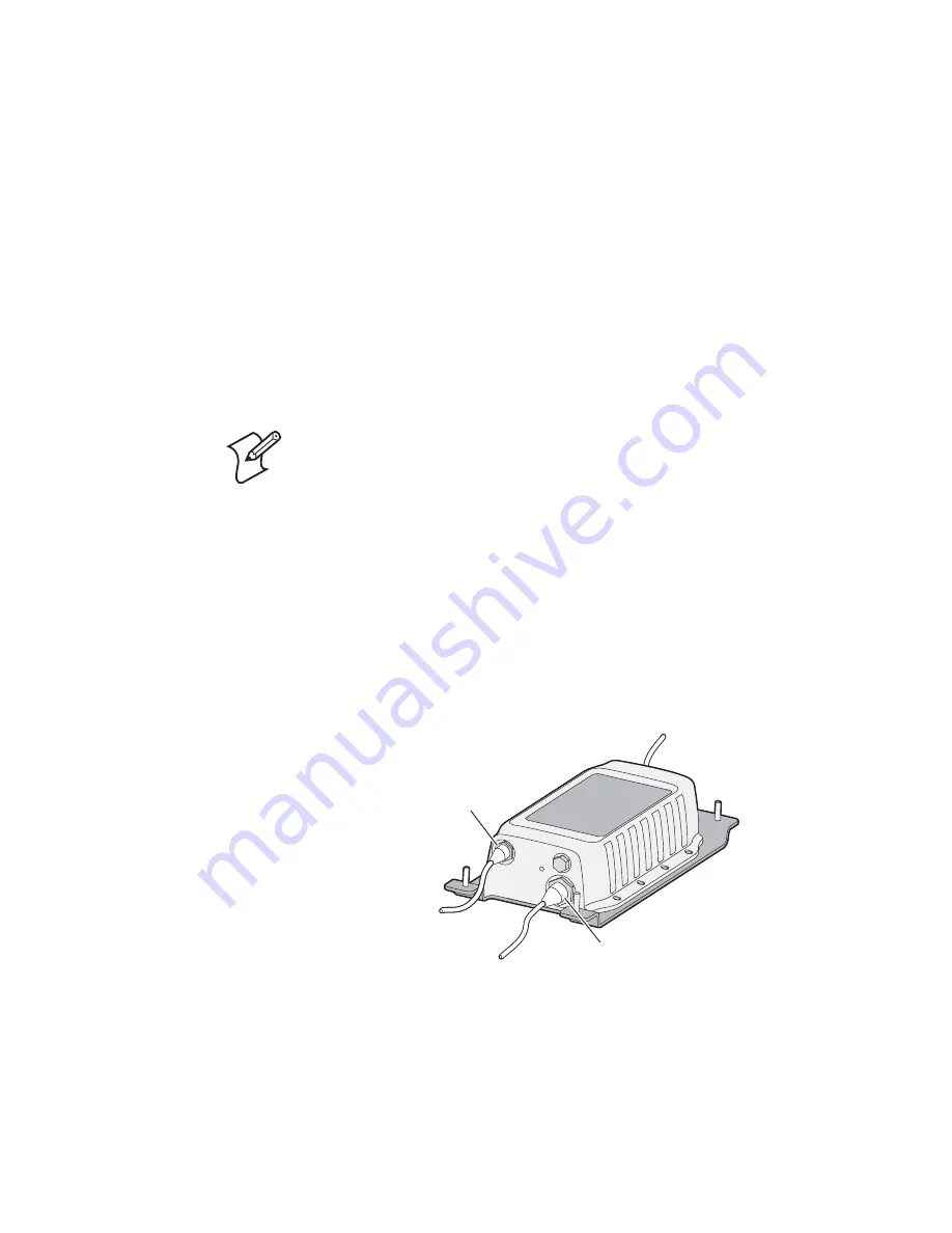
Connect the power, data, and antenna cables to the IV7. Do 
not connect the cables to any other component.

3

Position the IV7 in its mounting location on the back side of 
the load back rest. The IV7 label should face forward.

4

From the front of the load back rest, slide the mounting 
brackets onto the bolts on the IV7 baseplate.

Note:

 The IV7 requires 6-60 VDC at up to 4.5A for 

operation. Consult the vehicle manufacturer or your vehicle 
maintenance company for specific information on appropriate 
power connection and mounting locations.

To 6-60 VDC

To PC serial port 
and GPIO devices

Power port

Data port

To RFID antenna
(up to 4)

Summary of Contents for IV7

Page 1: ...IV7 Vehicle Mount Reader Instructions ...

Page 2: ...4 Understanding the Ports 5 Choosing a Mounting Location 6 Following Cable Safety Guidelines 8 Installing the IV7 9 Sending Commands to the IV7 12 About the GPIO Interfaces 12 IV7 Data Port Pin Assignments 13 IV7 Power Port Pin Assignments 14 Where to Go for More Information 14 Specifications 15 Patent Information 15 ...

Page 3: ...orts on the IV7 and how to install the IV7 and an RFID antenna on the load back rest Out of the Box When you unpack the IV7 save the packaging in case you need to ship or store the IV7 The reader comes with a documentation packet that includes safety and compliance statements and these instructions Government regulatory agencies require that this RFID reader only use approved antennas Therefore th...

Page 4: ...d include mounting brackets and hardware 865 869 MHz P N 805 816 001 915 MHz P N 805 816 002 You can connect up to four antennas to the IV7 Appropriate antenna cables for your IV7 Intermec offers these cable kits for load back rest installations Kit with standard SMA connector for 865 869 MHz P N 203 719 003 12 ft cable or P N 203 719 004 20 ft cable Kit with reverse SMA connector for 915 MHz P N ...

Page 5: ...ignments see page 14 IV7 Power Indicator Power Port and Data Port Locations IV7 Antenna Port Locations Note The IV7 requires 6 60 VDC at up to 4 5A for operation Consult the vehicle manufacturer or your vehicle maintenance company for specific information on appropriate power connection and mounting locations Power indicator Data port Power port Antenna ports 4 places Note The IV7 ships with termi...

Page 6: ...ioned in the center or end channels as seen in the next illustrations IV7 and Antenna Mounting This illustration shows the IV7 mounted in the center channel and the antenna mounted in one of the end channels Center channel End channel End channel RFID antenna IV7 Removable wire way Note The adaptable load back rest includes a wire way for cable routing You can remove the wire way during cable rout...

Page 7: ... the best possible visibility for the forklift operator If the IV7 and antennas are mounted where they significantly reduce operator visibility the installation should be evaluated for compliance with the following safety standards American National Standard ASME B56 11 6 1992 Evaluation of Visibility from Powered Industrial Trucks ISO 13564 1 Powered industrial trucks Test methods for verificatio...

Page 8: ...age Make sure the cables will not be pinched or rubbed by moving parts on the vehicle You may need to sheath the cable to prevent it from being pinched Secure the cables at least every 15 cm 6 in throughout the length of the cable run Use adjustable clamps or tie wraps to secure the cables Use a snap in bushing if the cables pass through a firewall or other sheet metal Note Most vehicle manufactur...

Page 9: ...k rest 1 Unscrew the four 5 16 18 locknuts from the IV7 and remove the mounting brackets 2 Connect the power data and antenna cables to the IV7 Do not connect the cables to any other component 3 Position the IV7 in its mounting location on the back side of the load back rest The IV7 label should face forward 4 From the front of the load back rest slide the mounting brackets onto the bolts on the I...

Page 10: ...or clarity 6 Route the power and data cables as needed If necessary use adhesive tiedowns and the removable wire way on the load back rest to manage the cables Do not connect the cables yet 7 Position the antenna in its mounting location on the front of the load back rest 8 From the back of the load back rest slide the antenna mounting brackets onto the bolts on the antenna case 9 Install the four...

Page 11: ...le to the antenna If necessary use adhesive tie downs and the removable wire way on the load back rest to manage the antenna cables 11 Optional Install GPIO devices on the vehicle and connect the data cable to the devices 12 Connect the IV7 data cable to the vehicle mounted computer 13 Connect the IV7 power cable to the DC power source The power indicator turns green The IV7 is now ready to use 1 ...

Page 12: ...ct external controls to the GPIO interfaces which can then trigger IV7 operations All GPIO interfaces should be restricted to a maximum operating input voltage of 5 VDC To use higher input voltages you need to use an external voltage conditioning network such as resistor dividers or active regulators The GPIO interfaces can be accessed through the data port For pin assignments see the next section...

Page 13: ...cription 1 TXD from IV7 11 GPIO Return 1 2 RXD to IV7 12 GPIO Return 2 3 Ground 13 GPIO Return 3 4 CTS from IV7 14 GPIO Return 4 5 RTS to IV7 15 GPIO Return 5 6 5VDC 16 NC 7 GP Input 0 17 GP Output 0 8 GP Input 1 18 GP Output 1 9 GP Input 2 19 GP Output 2 10 GP Input 3 20 GP Output 3 2 5 7 9 12 14 16 18 20 1 4 6 8 10 13 15 17 19 3 11 ...

Page 14: ...versions of our current manuals To order printed versions of the Intermec manuals contact your local Intermec representative or distributor Visit the Intermec technical knowledge base Knowledge Central at intermec custhelp com to review technical information or to request technical support for your Intermec product Power Port Pin Assignments Pin Description 1 VDC 2 VDC 3 Ground 1 2 3 ...

Page 15: ... 6 286 763 6 288 629 6 360 208 6 384 712 6 404 325 6 429 775 6 486 769 6 501 807 6 525 648 6 639 509 6 645 327 6 677 852 6 768 414 6 784 789 6 816 063 6 830 181 6 838 989 6 859 190 6 906 615 6 919 793 6 944 424 7 075 413 7 103 087 7 106 196 7 117 374 7 121 467 7 123 129 7 158 046 7 158 091 There may be other U S and foreign patents pending Dimensions 9 5 cm x 23 6 cm x 34 3 cm 3 75 in x 9 3 in x 1...

Page 16: ...Instructions 943 100 002 P N 943 100 002 Worldwide Headquarters 6001 36th Avenue West Everett Washington 98203 U S A tel 425 348 2600 fax 425 355 9551 www intermec com 2007 Intermec Technologies Corporation All rights reserved ...

Reviews: