background image

  38

440 01 1051 02

Specifications are subject to change without notice.

3.  For operation with Propane gas, gas orifices 

MUST

 be

changed and manifold pressure 

MUST

 be 

maintained

  as

per 

Table 7. 

Orifices can be ordered through our distributor.

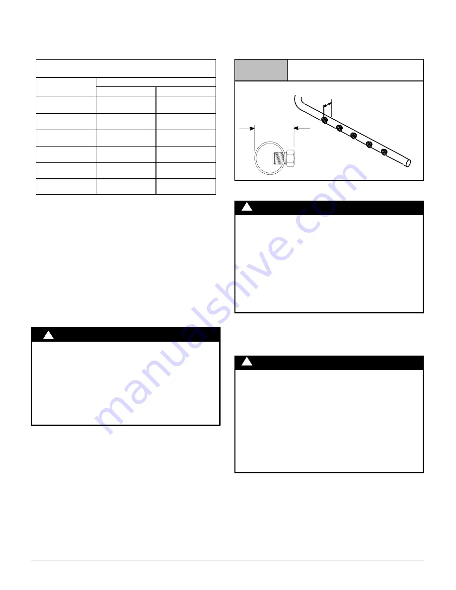
(See Figure 39)

High Altitude Input Rate = 

Nameplate Sea Level Input Rate x (Multiplier) *

{

Elevation

High  Altitude   Multiplier

Natural  Gas

Propane Gas

2001

- 3000

{

(609.9 

 914.4)

{

0.95

0.90

3001

- 4000

(914.7 

 1219.2)

0.93

0.86

4001

- 5000

(1219.5 

 1524)

0.91

0.82

5001

- 6000

(1524.3 

 1828.8)

0.89

0.78

6001

- 7000

(1829.1 

 2133.6)

0.87

0.74

7001

- 8000

(2133.9 

 2438.4)

0.85

0.70

*

 Based on mid

range of elevation.

High Altitude Air Pressure Switch

Altitudes over 4,000

 (1219.2m) may require a different air

pressure switch than the one installed at the factory. Check parts

list for pressure switch and consult your distributor for part number

and availability. In Canada, provincial codes may govern

installation of switch. Check with governing authorities.

*

In the USA,

 derating of these furnaces at 2% (Natural Gas) 

and 4% (Propane Gas) has been tested and design

certified 

by CSA.

{

In Canada

, the input rating must be derated 5% (Natural Gas)

and 10% (Propane Gas) for altitudes of 2,000 to 4,500 (609.6 

to1371.6m) above sea level. Use the 2001 to 3000  (609.9 to 

914.4m) column in 

Table 6

 and 

Table 7

.

Changing Orifices for High Altitude

ELECTRICAL SHOCK, FIRE OR EXPLOSION

HAZARD
Failure to follow this warning could result in

personal injury, death, and/or property damage.
Turn OFF electric power at fuse box or service

panel and gas supply at manual valve in gas valve,

lockout and tag switch with a suitable warning

label, when installing orifices. Installation of

orifices requires a qualified service technician.

!

WARNING

NOTE:

 Main burner orifices can be changed for high altitudes.

1.  Disconnect gas line from gas valve.
2.  Remove manifold from furnace.
3.  Remove the orifices from the manifold and replace them

with properly sized orifices.

4.  Tighten orifices so it is seated and gas tight. 

(See

Figure 39

)

5.  Reinstall manifold. Ensure burners do 

NOT

 bind on new

orifices.

Natural Gas Input Rating Check

SEE CHECKS AND ADJUSTMENTS, Natural Gas Input Rating

Check

 in this manual. 

Figure 39

Changing Orifices


Measure from face of orifice

to the back side of the 

manifold.

1.11

(28.2mm)

1.21

(30.8mm)

Final Gas Piping Check

FIRE OR EXPLOSION HAZARD
Failure to follow this warning could result in

personal injury, death, and/or property damage.
Never test for gas leaks with an open flame. Use a

commercially available soap solution made

specifically for the detection of leaks to check all

connections. A fire or explosion could result

causing property damage, personal injury and/or

loss of life.

!

WARNING

1.  The furnace and the equipment shut off valve must be

disconnected from the gas supply piping system during any

pressure testing of that system at test pressures in excess

of 

1

/

2

 PSIG. Close the manual shut

off valve before testing

at such pressures.

RISQUE D

INDENDIE OU D

EXPLOSION

Le non

respect des avertissements de sécurité

pourrait d

entrainer des blessures graves, la mort

ou des dommages matériels.
Ne jamais utiliser une flamme nue por vérifier la

présence des fuites de gaz. Pour la vérification de

tous les joints, utiliser plutôt une solution

savonneuse commerciale fabriquée

spécifiquement pur la détection des fuites de gaz.

Un incendie ou une explosion peut entrainer des

dommages matériels, des blessures ou la mort.

!

AVERTISSEMENT

2.  When installation is complete, test all pipe connections for

leaks with the gas pressure less than 

1

/

2

 PSIG to the gas

valve.

3.  The furnace must be isolated from the gas supply system by

closing the equipment shut off valve during any pressure

testing of the gas supply system at test pressure equal to or

less than 

1

/

2

  PSI.

4.  Apply a commercial soap solution to all joints to test for

leaks. Correct any leaks indicated by bubbles.

5.  Correct even the smallest leak at once.

6.  Check for leaks at gas valve and orifice connections to the

burner manifold while the furnace is operating.

Summary of Contents for C9MPX

Page 1: ...Installation Requirements 4 INSTALLATION 6 Combustion Ventilation Air 10 Vent Combustion Air Piping 14 Concentric Vent Termination 32 Gas Supply and Piping 34 Electrical Wiring 39 Ductwork and Filter...
Page 2: ...t above grade directly in line with the exhaust vent terminal for the horizontally vented gas fueled heating appliance or equipment The sign shall read in print size no less than one half 1 2 inch in...

Page 3: ...ondensate Drain Trapped Manual Gas Shut Off Upstream of Furnace Drip Leg Gas Valve turned ON Type of Gas Natural Propane Filter Type and Size Calculated Firing Rate See Checks and Adjustments Section...

Page 4: ...sult in personal injury death and or property damage This furnace is not designed for use in mobile homes trailers or recreational vehicles WARNING CUT HAZARD Failure to follow this caution may result...

Page 5: ...following 1 Thoroughly read this manual and labels on the unit This will help you understand how your unit operates and the hazards involved with gas and electricity 2 Do not use this unit if any part...

Page 6: ...ing could result in personal injury or death Do NOT operate furnace in a corrosive atmosphere containing chlorine fluorine or any other damaging chemicals which could shorten furnace life Refer to Com...

Page 7: ...g ignition input rate temperature rise and venting according to these instructions CARBON MONOXIDE POISONING HAZARD FaiIure to follow this warning could result in personal injury or death Do NOT opera...

Page 8: ...panels Note On the Direct Vent furnace the vent pipe attaches to the furnace through the side panels The combustion air pipe attaches to the top panel or to the alternate location on the side panel O...

Page 9: ...111 16 175 16 215 8 21 4 131 4 24 47 8 215 8 17 8 297 8 273 16 913 16 3311 16 KO KO KnockOut 609 6 30 2 249 2 31 7 73 549 3 27 109 5 122 2 758 8 690 6 549 3 855 7 439 7 42 9 123 8 177 8 47 6 469 9 723...

Page 10: ...the National Fuel Gas Code NFGC ANSI Z223 1 NFPA 54 2009 in the U S 2 Sections 8 2 8 3 8 5 8 6 8 7 and 8 8 of National Standard of Canada Natural Gas and Propane Installation Code NSCNGPIC CSA B149 1...

Page 11: ...one permanent outdoor opening is used the opening requires a 1 sq in of free area per 3 000 BTUH 7 cm2 kW for combined input of all gas appliances in the space see Table 1 and b not less than the sum...

Page 12: ...75 kW 100 000 BTU 29 300 kW 125 000 BTU 36 625 kW ft3 m3 0 60 1 050 29 7 1 400 39 2 1 750 49 1 250 35 1 875 52 5 2 500 70 3 125 87 5 0 50 1 260 35 3 1 680 47 04 2 100 58 8 1 500 42 2 250 63 3 000 84 3...

Page 13: ...QUIRED based on good trade practices local codes and good judgement of the installer Manufacturer does NOT take responsibility for modifications made to existing equipment CARBON MONOXIDE POISONING HA...

Page 14: ...1527 __ F628 D2468 D2661 D2235 PVC D1785 D2241 F891 D2466 D2665 F656 D2564 CPVC F441 F442 F438 F493 ABS to PVC D3138 NOTE 1 In Canada all pipe fittings cements must conform to applicable CSA standards...

Page 15: ...ion such as Armaflex or other equivalent type of insulation 3 Insulate combustion air inlet piping when run in warm humid spaces Sizing Combustion Air and Vent Pipe Consult Table 3 select the proper d...

Page 16: ...water heater vent or other appliance s direct vent intake or exhaust 12 30 cm 12 30 cm N Clearance to the vent terminal of a dryer vent water heater vent or other appliances direct vent intake or exha...

Page 17: ...dryer or water heater vent or other appliance s direct vent intake or exhaust N Clearance to the vent terminal of a dryer vent water heater vent or other appliances direct vent intake or exhaust O Cle...

Page 18: ...prevent kinking buckling of the drain tube The clip should remain in the furnace between the door switch plate and the blower shelf Figure 10 during operation See Figure 20 for proper routing and ins...

Page 19: ...in tube will exit Install casing grommet black rubber 5 8 15 9mm ID grommet in loose parts bag Install the 1 2 CPVC street elbow on discharge of trap Install the black PVC tube connector 3 4 18 1mm PV...

Page 20: ...ain tee Install Vent Pipe grommet in side of casing Cut an appropriate length of 2 50 8mm PVC pipe long enough to exit the cabinet and connect the vent drain to either A standard field supplied 2 50 8...

Page 21: ...screws Move the caps to the top of the trap and mount the trap externally to the left side of the unit using the two 2 screws provided Cut the 5 8 15 9mm ID corrugated hose as shown above and fasten...

Page 22: ...burner compartment to the blower compartment and secure with screws Move the caps to the top of the trap and mount the trap externally to the right side of the unit using the two 2 screws provided Co...

Page 23: ...ther with the 2 short 1 2 12 7mm ID elbow tubes and connect the lower discharge port of the vent drain to the trap Secure all connections with clamps Install the vent pipe grommet into the casing Cut...

Page 24: ...t Mount the trap externally to the bottom side of the unit using the two screws provided in the location shown Cut the corrugated tube as shown in the illustration above Connect the corrugated hose fr...

Page 25: ...and secure with screws Remove knockout from the side of the furnace casing where drain tube will exit Mount the trap externally to the bottom side of the unit using the two screws provided in the loca...

Page 26: ...nockout from the side of the furnace casing where drain tube will exit Mount the trap externally to the bottom side of the unit using the two screws provided in the location shown Cut the corrugated t...

Page 27: ...to the bottom side of the unit using the two screws provided in the location shown Cut the corrugated tube as shown in the illustration above Connect the corrugated hose from the transition to the tr...

Page 28: ...e furnace for the application Preassemble the vent and combustion air piping from the furnace to the vent termination Do not cement the pipe joints until the pipe preassembly process is complete Combu...

Page 29: ...llow primer to dry before applying cement 3 Apply a thin coat of cement evenly in the socket Quickly apply a heavy coat of cement to the pipe end and insert pipe into fittings with a slight twisting m...

Page 30: ...IN 12 304 8mm MIN Vertical Termination 1 Figure 25 shows the proper installation and clearances for vertical vent termination The vertical roof termination should be sealed with a plumbing roof boot o...

Page 31: ...or 2 503 8mm maximum separation 25 22 02d Vent Combustion Air Exhaust 1 25 4mm Maximum Exhaust A A Inlet Figure 28 Sidewall Inlet Vent and Exhaust Air Termination Dimension A is touching or 2 50 8mm m...

Page 32: ...diction gas inspection authority municipal building department fire department etc should be consulted before installation to determine the need to obtain a permit Consignes sp ciales pour l installat...

Page 33: ...OTE A field supplied stainless steel screw may be used to secure the rain cap to the pipe instead of cementing when field disassembly is desired for cleaning See Figure 34 If assembly needs to be exte...

Page 34: ...snow level or grade whichever is greater 1 25 4mm max 12 304 8mm min 8 Install the rain cap and the small diameter pipe assembly in the Y concentric fitting and the large pipe assembly Ensure that the...

Page 35: ...ll the gas pipe grommet to the furnace side panel with the gas pipe entry If needed remove the 2 50 8mm hole plug from the plastic accessory bag and relocate to the open hole in the furnace side panel...

Page 36: ...ane gas is recommended Propane Conversion An accessory kit shall be used to convert to propane gas use see the furnace rating plate for the Propane conversion accessory kit part number FIRE EXPLOSION...

Page 37: ...to 914 4m column in Table 6 and Table 7 Table 7 LPG or PROPANE GAS MANIFOLD PRESSURE in wc HEATING VALUE BTU CU FT FURNACE INPUT BTU BURNER MEAN ELEVATION FEET ABOVE SEA LEVEL ft m 0 to 2000 2001 to...

Page 38: ...perly sized orifices 4 Tighten orifices so it is seated and gas tight See Figure 39 5 Reinstall manifold Ensure burners do NOT bind on new orifices Natural Gas Input Rating Check SEE CHECKS AND ADJUST...

Page 39: ...using two self tapping screws from bag 6 Apply two hole plugs from bag at left J Box location Thermostat Thermostat location has an important effect on the operation of the unit Follow instructions i...

Page 40: ...on outlet side of furnace 3 For furnaces installed without a cooling coil it is recommended that the outlet duct be provided with a removable access panel This panel should be accessible when the fur...

Page 41: ...with a minimum of 1 25 4mm insulation with indoor type vapor barrier Filters A Filter must be used Filters are not supplied with these furnaces but can be purchased from the distributor Use either fil...

Page 42: ...uct flanges on the furnace MUST be broken down to provide proper fit up to the subbase Use duct pliers to bend the duct flanges flat onto the furnace casing DO NOT bend the duct flanges inward toward...

Page 43: ...d on the right side of the furnace in order to run the copper or plastic tubing for the condensate drain line Checks and Adjustments NOTE Verify the input rate of the furnace FIRE OR EXPLOSION HAZARD...

Page 44: ...he smallest dial on the gas meter to make one complete revolution Refer to Example NOTE If meter uses a 2 cubic foot dial divide results seconds by two Example BTUH Natural Gas BTU Content No of Secon...

Page 45: ...g motor speed lead Note For motors with 4 speed leads it will be necessary to tape off the terminal of the motor speed lead removed from the Heat or Cool terminal with electrical tape since an open te...

Page 46: ...ntinuously while there are no other blower demands from furnace control Fan demands from furnace control for heat cool or G will override hard wired speed tap NOTE 3 EAC is NOT active for hard wired m...

Page 47: ...ff fuse is open Heartbeat Normal operation or no previous Diagnostic Code ON SOLID Soft Lockout Furnace Control Error 1 hr delay If code repeats immediately following power reset then replace control...

Page 48: ...48 440 01 1051 02 Specifications are subject to change without notice Wiring Diagram 9MPX...

Page 49: ...change without notice Models Dual Certified 9MPX060F12A2 9MPX080J12A2 9MPX080J16A2 9MPX100L20A2 Denotes Brand Save This Manual For Future Reference 95 Furnace Upflow Horizontal Downflow International...

Page 50: ...7 423 3 2 797 2 9 722 1 9 473 2 0 498 3 2 797 2 9 722 1 9 473 2 0 498 3 2 797 2 9 722 2 3 573 2 4 598 3 2 797 2 9 722 Limits Controls Rollout Switch oF oC Limit Control Setting oF oC Auxilliary Switc...

Page 51: ...3 0 m s max filter media Bellyband Location on Motor A Dimension A Model 9MPX inches mm 060F12 13 8 35 1 080J12 17 8 46 080J20 17 8 46 100L20 15 8 41 9 9MPX080J16 1 2 Denote Brand Exterrnal Static Pre...

Page 52: ...ied installer service agency local gas supplier or your distributor or branch for information or assistance The qualified installer or agency must use only factory authorized and listed kits or access...

Reviews: