background image

Cooling Model Heat Pump

DFS2A324K1A DFS2H324K1A
DFS2A330K1A DFS2H330K1A

DFS2A336K1A DFS2H336K1A

DFS2A/H 24, 30, 36

Duct Free Systems

51302618914

Nov 

06

421 01 9218 00

R

22

Installation, Start-Up, and Service  Instructions

CONTENTS

Page

SAFETY CONSIDERATIONS

 1

. . . . . . . . . . . . . . . . . . . . . . 

GENERAL

1

6

. . . . . . . . . . . . . . . . . . . . . . . . . . . . . . . . . . . . . 

INSTALLATION 7

15

. . . . . . . . . . . . . . . . . . . . . . . . . . . . . . 

Indoor Unit Installation 

 7

. . . . . . . . . . . . . . . . . . . . . . . . 

Outdoor Unit Installation 

9

. . . . . . . . . . . . . . . . . . . . . . . . 

Power Supply 

 10

. . . . . . . . . . . . . . . . . . . . . . . . . . . . . . . . 

Leak Test 

 10

. . . . . . . . . . . . . . . . . . . . . . . . . . . . . . . . . . . . 

Wiring Diagrams 

 12

13

. . . . . . . . . . . . . . . . . . . . . . . . . . 

START

UP  

14

. . . . . . . . . . . . . . . . . . . . . . . . . . . . . . . . . . 

System Checks

 14

. . . . . . . . . . . . . . . . . . . . . . . . . . . . . . . 

CARE AND MAINTENANCE

 14

. . . . . . . . . . . . . . . . . . . . . . 

Outdoor Units 

 14

. . . . . . . . . . . . . . . . . . . . . . . . . . . . . . . 

Indoor Units 

 14

. . . . . . . . . . . . . . . . . . . . . . . . . . . . . . . . . 

To Clean the Indoor Unit Front Panel 

 14

. . . . . . . . . . . 

To Clean Indoor Coil 

 14

. . . . . . . . . . . . . . . . . . . . . . . . . . 

Air Filters for Outdoor Units 

 14

. . . . . . . . . . . . . . . . . . . 

INDOOR UNITS

14

. . . . . . . . . . . . . . . . . . . . . . . . . . . . . . . . . . 

SERVICE  

15

. . . . . . . . . . . . . . . . . . . . . . . . . . . . . . . . . . . . . . 

TROUBLESHOOTING

16

19

. . . . . . . . . . . . . . . . . . . . . . . . 

SAFETY CONSIDERATIONS

Installing, starting up, and servicing air

conditioning equipment

can be hazardous due to system pressures, electrical components,

and equipment location (roofs, elevated structures, etc.).
Only trained, qualified installers and service mechanics should

install, start

up, and service this equipment.

Untrained personnel can perform basic maintenance functions

such as cleaning coils. All other operations should be performed

by trained service personnel.
When working on the equipment, observe precautions in the

literature and on tags, stickers, and labels attached to the equipment.
Follow all safety codes. Wear safety glasses and work gloves.

Keep quenching cloth and fire extinguisher nearby when brazing.

Use care in handling, rigging, and setting bulky equipment.

DANGER, WARNING, CAUTION, and

NOTE

The signal words

 DANGER, WARNING, CAUTION, 

and

NOTE

 are used to identify levels of hazard serious-

ness. The signal word 

DANGER

 is only used on

product labels to signify an immediate hazard. The

signal words

 WARNING,


CAUTION, 

and

 NOTE

 will

be used on product labels and throughout this manu-

al and other manuals that may apply to the product.

DANGER


 Immediate hazards which 

will

 result in se-

vere personal injury or death.

WARNING 

 Hazards or unsafe practices which 

could

result in severe personal injury or death.

CAUTION 

 Hazards or unsafe practices which

 may

 re-

sult in minor personal injury or product or property

damage.

NOTE 

 Used to highlight suggestions which 

will

 result in

enhanced installation, reliability, or operation.

Signal Words in Manuals

The signal word

 WARNING 

is used throughout this

manual in the following manner:

The signal word 

CAUTION 

is used throughout this

manual in the following manner:

Signal Words on Product Labeling

Signal words are used in combination with colors and/or

pictures on product labels.

WARNING

Safety Labeling and Signal Words

!

CAUTION

WARNING

!

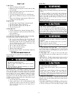
ELECTRICAL SHOCK HAZARD

Failure to follow this warning could result in personal

injury or death.
Before installing or servicing system, always turn off main

power to system and install lockout tag on disconnect.

There may be more than one disconnect switch.

!

WARNING

GENERAL

These instructions cover the installation, start

up and servicing of

DFC2A/DFC2H 

outdoor and 

DFF2A/DFF2H 

indoor units

cooling only and heat pump duct free systems. See Table 1 for

parts included. See Tables 2 and 3 for Physical Data.

Summary of Contents for DFS2A324K1A

Page 1: ...ER WARNING CAUTION and NOTE The signal words DANGER WARNING CAUTION and NOTE are used to identify levels of hazard serious ness The signal word DANGER is only used on product labels to signify an imme...

Page 2: ...units should be installed at a Mini mum length of 10 ft apart Maximum line length of 130 ft and vertical separation of 65 ft S Do not install indoor units near a direct source of heat such as direct s...

Page 3: ...emote Controller Mounting Bracket Remote Controller and Batteries Insulation for Indoor Fittings Owner s Manual Wall mounted Receiver RTX 1 8 1 1 1 1 1 Mounting Bracket with 2 screws 16 4 1 OPTIONAL N...

Page 4: ...ata Heat Pump Indoor Unit DFF2HH24K1A DFF2HH30K1A DFF2HH36K1A Cooling Capacity Btu h 22 800 29 000 33 000 Watt 6 682 8 499 9 672 Efficiency Cooling SEER SEER 13 13 13 Heating Capacity Btu h 22 600 28...

Page 5: ...V E E L S L L A W N O I T C E N N O C E N I L D I U Q I L E R A L F E L A M H N O I T C E N N O C E N I L N O I T C U S E R A L F E L A M G E T O M E R D E R A R F N I H C T I W S E D I R R E V O R E...

Page 6: ...D N A E D I S N A F N O E C N A R A E L C M U M I N I M 2 W O L L A L L A W G N I C A F N A F H T I W 2 1 E D I S L I O C D N E R O S S E R P M O C N O E C N A R A E L C M U M I N I M T E E F 2 D N A...

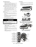
Page 7: ...refrigerant lines drainage hose and control cable passage as shown in Fig 5 1 Mark the center of the hole to be drilled according to the refrigerantline routing used and dimensions shown in Fig 4 2 M...

Page 8: ...mly fastened WARNING MAKE DRAINAGE CONNECTIONS 1 Connect the unattached end of the drainage tube to the drainage hose outlet 2 Seal the drainage connection to prevent leakage 3 Make sure there are no...

Page 9: ...ge tube can be connected to the outdoor unit to remove condensation formed during heating mode operation FIRE HAZARD Failure to follow this warning could result in personal injury death and or propert...

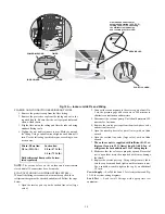
Page 10: ...ngs are connected air must be expelled then refrigerant charge must be checked and adjusted Follow the steps below 1 Open the service port cap on the suction line valve large valve 2 Connect the vacuu...

Page 11: ...out notice 3095897 Table 5 Electrical Data Outdoor Units 208 230 1 60 UNIT VOLTAGE MCA MOCP FULL LOAD AMPS FAN MOTOR AMPS COMPRESSOR AMPS COMPRESSOR LOCKED ROTOR AMPS DFC2A3 24K1A 208 230VAC 11 0 20...

Page 12: ...H T C F N A F R O T O M 6 5 4 3 2 1 BLK Y E L GR R E D B R N W H T B R N W H T 6 1 5 4 3 2 S V R K L B L B K R C T P BLUE BLUE S R B R B L U E B LK B R D E R 1 2 3 4 5 1 2 3 4 5 1 2 3 4 5 Y A L P S I...

Page 13: ...L B E D E R 7 K 9 K 8 K 2 1 1 J 1 O F C F P M O C O N O C E L L U F P M O C P M O C O N O C E P M O C O N O C E P M O C L L U F W H T C F N A F R O T O M 6 5 4 3 2 1 BLK Y E L GR R E D B R N W H T B R...

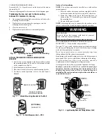
Page 14: ...install lockout tag 2 Using a garden hose or other suitable equipment flush coil from the outside to remove dirt Be sure to flush all dirt and debris from drain holes in base of unit Fan mo tors are...

Page 15: ...e start of each cooling season Check the flow by pouring water into the drain Clean or Replace Drain Pan The drain pan should only be cleaned or replaced by a qualified service technician 1 Place a pl...

Page 16: ...ect resistance Check for proper connection Replace thermistor if necessary 3 Flashes Low Pressure Check system pressures Check refrigerant charge Check thermistors TH1 and TH2 for correct resistance 4...

Page 17: ...4 13 25 35 6 2 1 8 1 0 11 75 12 22 12 70 37 4 3 1 8 1 0 11 28 11 73 12 18 39 2 4 1 8 1 0 10 83 11 25 11 68 41 0 5 1 8 1 0 10 40 10 80 11 21 42 8 6 1 8 1 0 9 986 10 370 10 76 44 6 7 1 8 1 0 9 595 9 960...

Page 18: ...2 2 1 2 2 264 2 352 2 441 118 4 48 2 3 1 3 2 192 2 227 2 364 120 2 49 2 3 1 3 2 122 2 206 2 291 122 0 50 2 3 1 3 2 055 2 137 2 220 123 8 51 2 3 1 3 1 990 2 070 2 151 125 6 52 2 3 1 3 1 928 2 006 2 08...

Page 19: ...fan motor In Heat mode Delayed start for indoor fan motor Normal software delay maximum of 20 sec Clogged air filters Clean filters Low Capacity Lack of refrigerant Ice formation on the evapora tor co...

Reviews: