29
Hoisting the main body of the air conditioner
The primary step for installing the indoor unit.
S
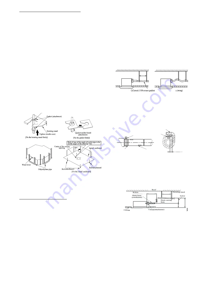
When attaching the hoisting stand on the hoisting screw, do
use nut and gasket individually at the upper and lower of
the hoisting stand to secure it. The use of gasket anchor
board can prevent gasket break off.
Use install cardboard.
S
Refer to the install cardboard about the dimension of
ceiling opening.
S
The central mark of the ceiling opening is marked on the
install cardboard.
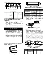
1. Install the install cardboard on the unit by bolt (3 pieces)
and fix the angle of the drainage pipe at the outlet vent by
bolt.
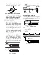
2. Adjust the unit to the suitable install place. Refer to Fig. 59.
3. Check if the unit is horizontal.
4. The inner drainage pump and bobber switch are included in
the indoor unit, check if the 4 angle of every unit are
horizontal by the water lever. If the unit is slanted toward
the opposite of the coagulate water flow, there may be a
malfunction of the bobber switch and lead water drop.)
5. Backout the gasket anchor board used to prevent gasket
break off and tighten the nut on it.
6. Backout the install cardboard.
Nut supplied at scene
Fig. 60
-
Hoisting the main body
NOTE
: Tighten the nuts and bolts to prevent the air conditioner
from breaking off.
CONNECTION OF THE REFRIGERANT PIPE
Connection of the Refrigerant Pipe
When connecting the pipe to the unit or backout from the unit, use
both a spanner and a torque wrench.
When connecting, smear both inside and outside of the flare nut
with freeze motor oil, screw it by hand and then tighten with a
spanner.
Refer to form 1 to check if the wrench had been tightened (too
tight would mangle the nut and lead leakage).
Examine the connection pipe to see if it had a gas leak, then take
the treatment of heat insulation. Only use a median sponge to
entwine the wiring interface of the gas pipe and heat preservation
sheath of the gas collection tube.
DRAINAGE HOSE
1. Install the drain hose.
S
The diameter of the drain hose should be equal or bigger
than the connection pipe’s. (The diameter of the polythene
pipe: Outer diameter 1 in (25 mm) Surface thickness
0.06
in (1.5 mm).
S
The drain hose should be short and the drooping gradient
should be less than 1/100 to prevent the formation of an air
bubble. If the drain hose does not has enough of a drooping
gradient, a drain raising pipe should be added.
S
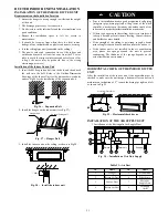
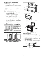
To prevent a bend in the drain hose, the distance between
the hoisting stand should is 3.28 to 4.92 ft (1 to 1.5 m) (see
Fig.61).
3.28 to 4.92 ft (1 to 1.5 m)
3.28 to 4.92 ft (1 to 1.5 m)
Fig. 61
-
Drain Hose
S
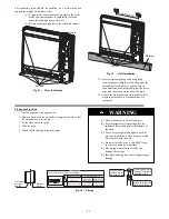
Use the drain hose and clamp attached. Insert the drain hose
into the drain vent, and then tighten the clamp.
S
Entwine the big sponge on the clamp of drain hose to
insulate heat.
S
Heat insulation should be applied to the indoor drain hose.
Sponge(attachment)
Clamp(attachment)
Below
1/6 in (4 mm)
Clamp
Drain hose
Sponge (gray)
Fig. 62
-
Drain Hose
NOTE
: Drain Setup pipe
S
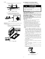
The install height of the drain raising pipe should less than
11 in. (280 mm).
S
The drain raising pipe should form a right angle with the
unit, and distance to unit should not beyond 11.81 in.
(300mm).
11 4/5 in (300 mm)
3.2 8-4.9 2
ft (1-1.5 m)
11 in (2 80 mm)
8 2/3 in (220 mm)
19
2
/3
(500
mm)
Fig. 63
-
Drain Setup Pipe


