INSTALLATION INSTRUCTIONS
Gas Furnace: (F/G)9MVE
12
440 01 4400 03
Specifications subject to change without notice.
Table 4
Minimum Space Volumes for 100% Combustion, Ventilation and Dilution Air from Outdoors
OTHER THAN FAN‐ASSISTED TOTAL
(1,000'S BTUH GAS INPUT RATE)
FAN‐ASSISTED TOTAL
(1,000'S BTUH GAS INPUT RATE)
ACH
30
40
50
40
60
80
100
120
140
Space Volume Ft
3
(M
3
)
0.60
1,050
(29.7)
1,400
(39.6)
1,750
(49.5)
1,400
(39.6)
1,500
(42.5)
2,000
(56.6)
2,500
(70.8)
3,000
(84.9)
3,500
(99.1)
0.50
1,260
(35.6)
1,680
(47.5)
2,100
(59.4)
1,680
(47.5)
1,800
(51.0)
2,400
(67.9)
3,000
(84.9)
3,600
(101.9)
4,200
(118.9)
0.40
1,575
(44.5)
2,100
(59.4)
2,625
(74.3)
2,100
(59.4)
2,250
(63.7)
3,000
(84.9)
3,750
(106.1)
4,500
(127.3)
5,250
(148.6)
0.30
2,100
(59.4)
2,800
(79.2)
3,500
(99.1)
2,800
(79.2)
3,000
(84.9)
4,000
(113.2)
5,000
(141.5)
6,000
(169.8)
7,000
(198.1)
0.20
3,150
(89.1)
4,200
(118.9)
5,250
(148.6)
4,200
(118.9)
4,500
(127.3)
6,000
(169.8)
7,500
(212.2)
9,000
(254.6)
10,500
(297.1)
0.10
6,300
(178.0)
8,400
(237.8)
10,500
(297.3)
8,400
(237.8)
9,000
(254.6)
12,000
(339.5)
15,000
(424.4)
18,000
(509.2)
21,000
(594.1)
0.00
NP
NP
NP
NP
NP
NP
NP
NP
NP
NP = Not Permitted
CONDENSATE TRAP
!
CAUTION
FROZEN AND BURST WATER PIPE HAZARD
Failure to protect against the risk of freezing may result in
property damage.
Special precautions MUST be made if installing furnace in an
area which may drop below freezing. This can cause improper
operation or damage to equipment. If furnace environment has
the potential of freezing, the drain trap and drain line must be
protected. The use of accessory drain trap heaters, electric
heat tape and/or RV antifreeze is recommended for these
installations.
!
CAUTION
PROPERY DAMAGE HAZARD
Failure to follow this caution may result in burst water pipes
and/or property damage.
If a condensate pump is installed, a plugged condensate drain
or a failed pump may cause the furnace to shut down. Do not
leave the home unattended during freezing weather without
turning off water supply and draining water pipes or otherwise
protecting against the risk of frozen pipes.
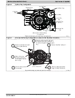
Condensate Trap
−
Upflow Orientation
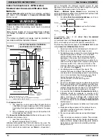
When the furnace is installed in the upflow position, it is not
necessary to relocate the condensate trap or associated
tubing. Refer to
for upflow condensate trap
information. Refer to Condensate Drain section for information
how to install the condensate drain.
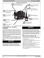
Condensate Trap
−
Downflow
Orientation
When the furnace is installed in the downflow position, the
condensate trap will be initially located at the upper left corner
of the collector box, as received from the factory. See the top
. When the furnace is installed in the
downflow orientation, the condensate trap must be relocated
for proper condensate drainage. See the bottom image in
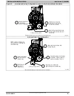
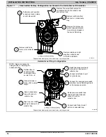
To Relocate the Condensate Trap:
Orient the furnace in the downflow position.
shows the condensate trap and tubing before and
to begin the trap conversion.
Refer to Condensate Drain section for information how to install
the condensate drain.


