

INSTALLATION INSTRUCTIONS
Gas Furnace: (F/G)9MVE
440 01 4400 03
27
Specifications subject to change without notice.
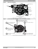
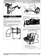
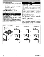
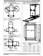
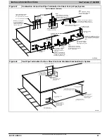
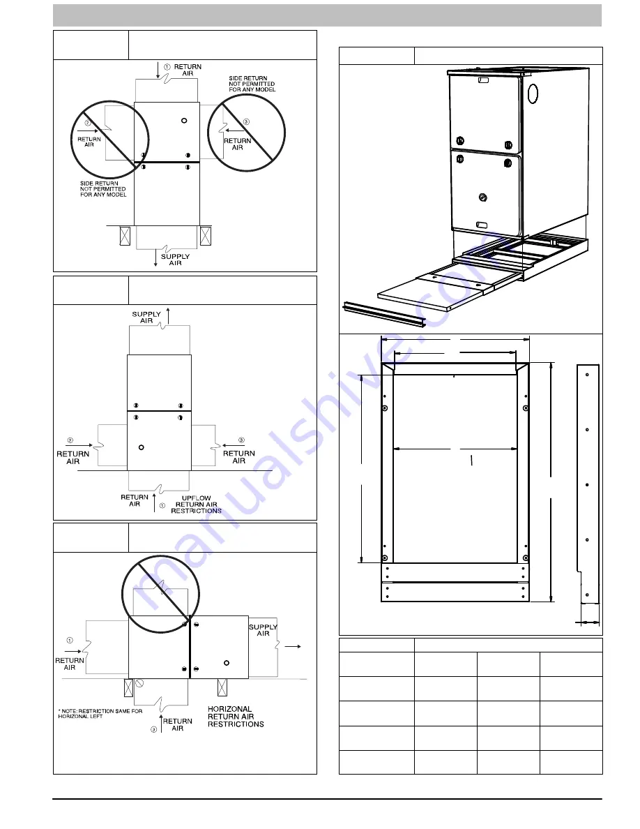
Figure 27
Downflow Return Air
Configurations and Restrictions
L10F033
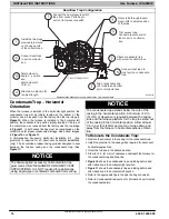
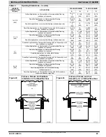
Figure 28
Upflow Return Air Configurations
and Restrictions
L10F032
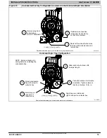
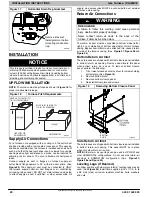
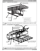
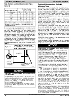
Figure 29
Horizontal Return Air
Configurations and Restrictions
HORIZONTAL TOP
RETURN NOT
PERMITTED FOR
ANY MODEL
SIDE RETURN AIR NOT PERMITTED FOR 2000 CFM AND
ABOVE OF AIR FLOW
L10F034
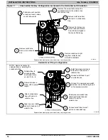
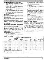
External Filter Cabinet Configurations
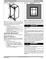
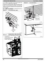
Figure 30
Accessory Bottom Filter Rack
L10F031
B
A
28
−
7/16
(722.2)
22
−
5/16
(566.4)
2
−
3/16
(55.5)
A
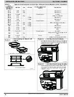
Table 9
Dimensional Drawing
−
in. (mm)
KIT NO.
FURNACE
WIDTH
A
B
NAHB00501FF
14
−
3/16
(360.4)
11
−
3/8
(289)
14
−
1/4
(362)
NAHB00601FF
17
−
1/2
(444.5)
14
−
5/8
(371.5)
17
−
5/8
(447.7)
NAHB00701FF
21
(533.4)
18
−
1/8
(460.4)
21
−
1/8
(536.6)
NAHB00801FF
24
−
1/2
(622.3)
21
−
5/8
(549.3)
24
−
5/8
(625.5)


