INSTALLATION INSTRUCTIONS
Gas Furnace: (F/G)9MVE
440 01 4400 03
5
Specifications subject to change without notice.
CANADA: NSCNGPIC. For a copy, contact Standard
Sales, CSA International, 178 Rexdale Boulevard,
Etobicoke (Toronto), Ontario, M9W 1R3, Canada.
Combustion and Ventilation Air
US: Section 9.3 of the NFPA54/ANSI Z223.1
−
2012,
Air for Combustion and Ventilation
CANADA: Part 8 of the CAN/CSA B149.1
−
2010,
Venting Systems and Air Supply for Appliances
Duct Systems
US and CANADA: Air Conditioning Contractors
Association (ACCA) Manual D, Sheet Metal and Air
Conditioning Contractors National Association
(SMACNA), or American Society of Heating,
Refrigeration, and Air Conditioning Engineers (ASHRAE)
2005 Fundamentals Handbook Chapter 35.
Acoustical Lining and Fibrous Glass
Duct
US and CANADA: current edition of SMACNA, NFPA
90B as tested by UL Standard 181 for Class I Rigid Air
Ducts
Gas Piping and Gas Pipe Pressure
Testing
U.S.A.: NFPA 54/ANSI Z223.1
−
2012, NFGC; Chapters
5, 6, 7, and 8 and national plumbing codes.
CANADA: CAN/CSA
−
B149.1
−
2010, Parts 4, 5, 6 and
9.
In the state of Massachusetts:
This product must be installed by a licensed plumber or
gas fitter.
When flexible connectors are used, the maximum
length shall not exceed 36
−
in. (914 mm).
When lever type gas shutoffs are used they shall be
T
−
handle type.
The use of copper tubing for gas piping is not
approved by the state of Massachusetts.
Electrical Connections
U.S.A.: National Electrical Code (NEC) ANSI/NFPA
70
−
2011
CANADA: Canadian Electrical Code CSA C22.1
Condensate Drain Connection
US: National Standard Plumbing Code 2009, Section 8.7.
Canada: National Plumbing Code of Canada 2010 in
Canada.
Electrostatic Discharge (ESD)
Precautions Procedure
CAUTION
!
FURNACE RELIABILITY HAZARD
Failure to follow this caution may result in unit com-
ponent damage.
Electrostatic discharge can affect electronic compon-
ents. Take precautions during furnace installation and
servicing to protect the furnace electronic control. Pre-
cautions will prevent electrostatic discharges from per-
sonnel and hand tools which are held during the pro-
cedure. These precautions will help to avoid exposing
the control to electrostatic discharge by putting the
furnace, the control, and the person at the same elec-
trostatic potential.
1. Disconnect all power to the furnace. Multiple
disconnects may be required. DO NOT TOUCH THE
CONTROL OR ANY WIRE CONNECTED TO THE
CONTROL PRIOR TO DISCHARGING YOUR BODY’S
ELECTROSTATIC CHARGE TO GROUND.
2. Firmly touch the clean, unpainted, metal surface of the
furnace chassis which is close to the control. Tools held
in a person’s hand during grounding will be satisfactorily
discharged.
3. After touching the chassis, you may proceed to service
the control or connecting wires as long as you do nothing
to recharge your body with static electricity (for example;
DO NOT move or shuffle your feet, do not touch
ungrounded objects, etc.).
4. If you touch ungrounded objects (and recharge your
body with static electricity), firmly touch a clean,
unpainted metal surface of the furnace again before
touching control or wires.
5. Use this procedure for installed and uninstalled
(ungrounded) furnaces.
6. Before removing a new control from its container,
discharge your body’s electrostatic charge to ground to
protect the control from damage. If the control is to be
installed in a furnace, follow items 1 through 4 before
bringing the control or yourself in contact with the
furnace. Put all used and new controls into containers
before touching ungrounded objects.
7. An ESD service kit (available from commercial sources)
may also be used to prevent ESD damage.
Accessories
See Specification Sheets for a list of accessories for this
product.
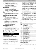
Table 2
Loose Parts Bag Contents
(shipped in blower compartment)
QUANTITY DESCRIPTION
(Provided in Loose Parts Bag)
1
Outlet Choke Plate
−
see
NOTE
(used with 40k BTUH furnaces, only)
1
Air Intake Pipe Flange
1
Vent Pipe Flange
2
Pipe Flange Gaskets
10
Sharp Tip Screws (Vent and Inlet Flanges)
1
Vent Pipe Coupling
2
Vent Pipe Coupling Clamps
1
Pressure Switch Tube
1
Rubber Drain Elbow
4
Drain Elbow Clamps
1
1/2”CPVC to 3/4” PVC Pipe Adapter
1
Gas Line Grommet
1
Gas Line Knockout Plug
1
Junction Box Cover
1
Junction Box Base
1
Green Ground Screw
3
Blunt Tip Screws (Junction Box)
1
Thermostat Wire Grommet
Provided separately in furnace
1
Drain Extension Tube
−
“Z” Pipe
NOTE
: Only used on 40K BTUH furnaces from 0 to 2000 ft. (0
to 610m) above sea level for total equivalent vent lengths under
10 ft.


