background image

SERVICE AND TECHNICAL SUPPORT MANUAL

Gas Furnace: (F/G)9MXE

Specifications  subject to change without notice.

20

440 04 4311 08

NOTE

:  Do 

NOT 

blow into tube with tube connected to the

pressure switch.

9. Clean pressure switch port on collect box with a small

wire. Shake any water out of pressure switch tube.

10. Reconnect tube to pressure switch and pressure switch

port.

11. Remove the relief tube from the port on the collector box

and the trap.

12. Clean the relief port on collect box and the trap with a

small wire. Shake any water out of the tube.

13. Reconnect relief tube to trap and collector box ports.

Cleaning Condensate Drain and Trap

NOTE

:  If the condensate trap is removed, a new gasket

between the trap and collector box is required. Verify a
condensate trap gasket is included in the service kit or obtain
one from your local distributor.

1. Disconnect power at external disconnect, fuse or circuit

breaker.

2. Turn off gas at external shut-off or gas meter.
3. Remove control door and set aside.
4. Turn electric switch on gas valve to OFF.
5. Disconnect external drain from condensate drain elbow

or drain extension pipe inside the furnace and set aside.

6. Disconnect the condensate trap relief hose from collector

box port and condensate trap.

NOTE

:  If condensate has a heat pad attached to the trap,

trace the wires for the pad back to the connection point and
disconnect the wires for the heat pad.

7. Remove the screw that secures the condensate trap to

the collector box, remove the trap and set aside.

8. Remove the trap gasket from the collector box if it did not

come off when the trap was removed.

9. Discard the old trap gasket.

10. Rinse condensate trap in warm water until trap is clean.

11. Flush condensate drain lines with warm water.

Remember to check and clean the relief port on the

collector box.

12. Shake trap dry.
13. Clean port on collector box with a small wire.

To re-install Condensate Drain and Trap:

1. Remove adhesive backing from condensate trap gasket
2. Install gasket on collector box
3. Align the condensate trap with the drain opening on the

collector box and secure the trap with the screw

4. Attach the relief hose to the relief port on the condensate

trap and collector box.

5. Secure tubing to prevent any sags or traps in the tubing.
6. Connect condensate drain elbow or drain extension

elbow to the condensate trap

7. Connect the leads of the condensate heat pad (if used)
8. Connect external drain piping to the condensate drain

elbow or drain extension pipe.

9. Turn gas on at electric switch on gas valve and at

external shut-off or meter

10. Turn power on at external disconnect, fuse or circuit

breaker.

11. Run the furnace through two complete heating cycles to

check for proper operation

12. Install control door when complete.

Checking Heat Pad Operation (If Applicable)

In applications where the ambient temperature around the

furnace is 32

_

F (0

_

C) or lower, freeze protection measures are

required. If this application is where heat tape has been

applied, check to ensure it will operate when low temperatures

are present.

NOTE

:  The Heat Pad, when used, should be wrapped around

the condensate drain trap. There is no need to use heat tape
within the furnace casing. Most heat tapes are temperature

activated, and it is not practical to verify the actual heating of
the tape. Check the following:

1. Check for signs of physical damage to heat tape such as

nicks, cuts, abrasions, gnawing by animals, etc.

2. Check for discolored heat tape insulation. If any damage

or discolored insulation is evident, replace heat tape.

3. Check that heat tape power supply circuit is on.

Cleaning Heat Exchangers

The following items must be performed by a qualified service

technician.

Primary Heat Exchangers

If the heat exchangers get an accumulation of light dirt or dust

on the inside, they may be cleaned by the following procedure:

NOTE

:  If the heat exchangers get a heavy accumulation of

soot and carbon, both the primary and secondary heat
exchangers should be replaced rather than trying to clean them
thoroughly due to their intricate design. A build

up of soot and

carbon indicates that a problem exists which needs to be
corrected, such as improper adjustment of manifold pressure,
insufficient or poor quality combustion air, improper vent

termination, incorrect size or damaged manifold orifice(s),
improper gas, or a restricted heat exchanger (primary or
secondary). Action must be taken to correct the problem.

1. Turn off gas and electrical supplies to furnace.
2. Remove control door.
3. Disconnect wires or connectors to flame rollout switch,

gas valve, igniter, and flame sensor.

4. Using backup wrench, disconnect gas supply pipe from

furnace gas control valve.

5. Remove two screws attaching top filler plate and rotate

upwards to gain access to screws attaching burner

assembly to cell panel.

6. Remove screws attaching burner assembly to cell panel.

(See 

Figure 9

)

NOTE

:  Burner cover, manifold, gas valve, and burner

assembly should be removed as one assembly.

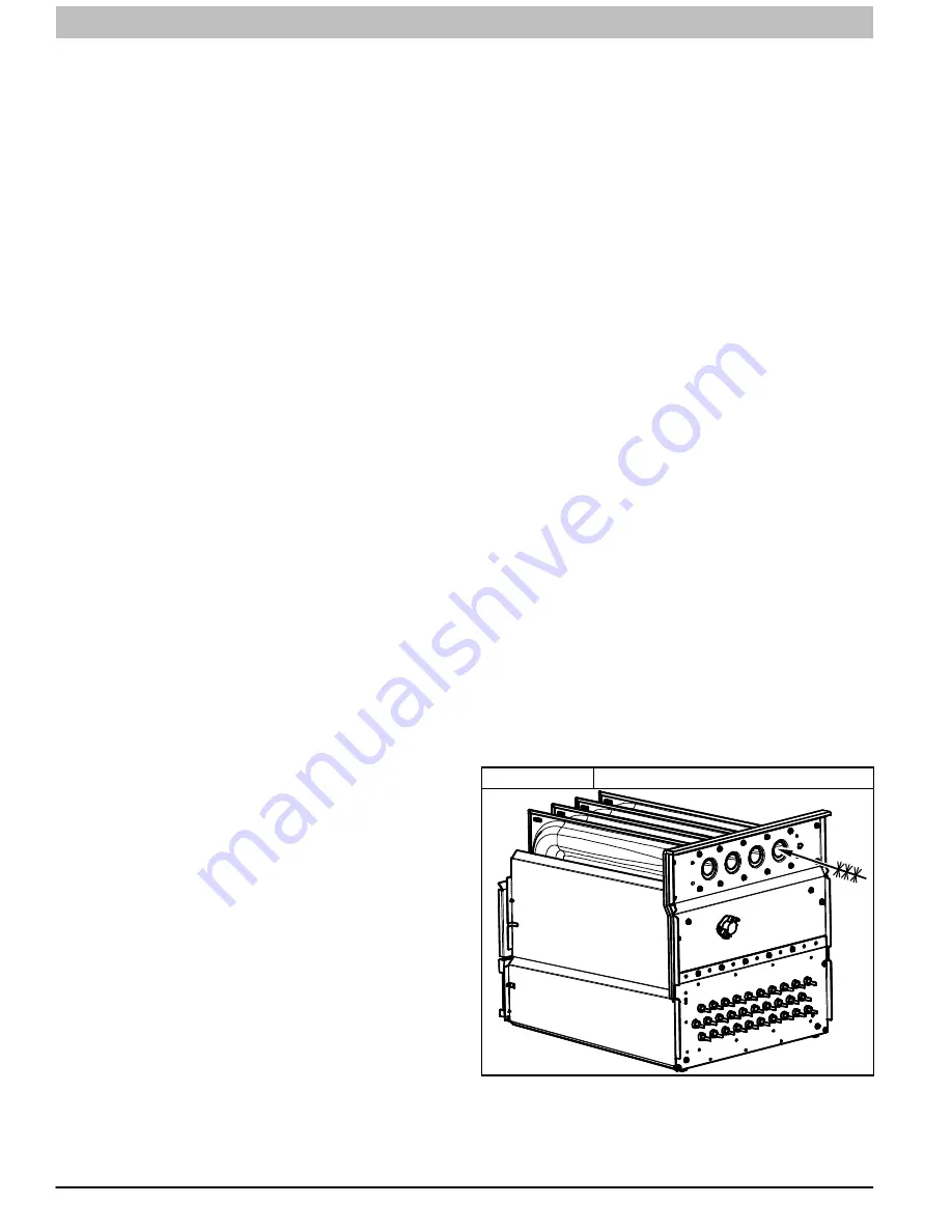
7. Clean heat exchanger openings with a vacuum and a

soft brush. (See 

Figure 12

)

Figure 12

Cleaning Heat Exchanger Cell

NOTE

:  After cleaning, inspect the heat exchangers to ensure

they are free of all foreign objects that may restrict flow of

combustion products.

Summary of Contents for F9MXE0401410A

Page 1: ...uct labels The signal word WARNING is used throughout this manual in the following manner Safety alert symbol When you see this symbol on the unit and in instructions or manuals be alert to the potential for personal injury TABLE OF CONTENTS START UP ADJUSTMENT AND SAFETY CHECK 4 PRIME CONDENSATE TRAP WITH WATER 4 PURGE GAS LINES 4 ADJUST TEMPERATURE RISE 10 ADJUST BLOWER OFF DELAY HEAT MODE 11 AD...

Page 2: ...death WARNING signifies hazards which could result in personal injury or death CAUTION is used to identify unsafe practices which may result in minor personal injury or product and property damage NOTE is used to highlight suggestions which will result in enhanced installation reliability or operation WARNING PERSONAL INJURY AND OR PROPERTY DAMAGE HAZARD Failure to carefully read and follow this w...

Page 3: ...stream of Furnace Drip Leg Gas Valve turned ON Type of Gas Natural Propane Filter Type and Size Check in box the Blower OFF Delay Jumper Heating Position for Fan Time OFF Setting 1 and 2 2 and 3 3 and 4 5 and 6 90 120 150 180 Calculated Input BTU Rate See Checks and Adjustments Section Heating Check Measured Line Pressure During Heat Measured Manifold Pressure Heat Temperature of Supply Air Heat T...

Page 4: ... switch CAUTION Before operating furnace check flame rollout manual reset switch for continuity If necessary press button to reset switch EAC 1 115vac terminal is energized whenever blower operates HUM 24vac terminal is only energized the draft inducer is energized in heating Prime Condensate Trap with Water CARBON MONOXIDE POISONING HAZARD Failure to follow these warnings could result in personal...

Page 5: ...T M PERCENT OF DERATE DERATE MULTIPLIER FACTOR 0 2000 0 610 0 1 00 2001 3000 610 914 4 6 0 95 3001 4000 914 1219 6 8 0 93 4001 5000 1219 1524 8 10 0 91 5001 6000 1524 1829 10 12 0 89 6001 7000 1829 2134 12 14 0 87 7001 8000 2134 2438 14 16 0 85 8001 9000 2438 2743 16 18 0 83 9001 10 000 2743 3048 18 20 0 81 Derate multiplier factors are based on midpoint altitude for altitude range NOTE For Canadi...

Page 6: ...ove regulator adjustment cap from gas valve pressure regulator See Figure 3 and turn adjusting screw 3 16 or smaller flat tipped screwdriver counterclockwise out to decrease input rate or clockwise in to increase input rate NOTICE DO NOT set low heat manifold pressure less than 2 8 in w c 697 Pa or more than 3 8 in w c 947 Pa for natural gas If required manifold pressure is outside this range chan...

Page 7: ...4VAC CONNECTIONS EAC TERMINAL 115 VAC 1 0 AMP MAX COOL SPARE2 SPARE1 COM BLUE 115 VAC L2 NEUTRAL CONNECTIONS 24 V THERMOSTAT TERMINALS HUMIDIFIER TERMINAL 24 VAC 0 5 AMP MAX 3 AMP FUSE LED OPERATION DIAGNOSTIC LIGHT 24VAC RED BLOWER SPEED SELECTION TERMINALS BL 1 XFMR Y1 DHUM HEAT OFF DELAY 120 180 90 150 ÏÏ ÏÏ ÏÏ ÏÏ ÏÏ ÏÏ ÏÏ NEUTRAL L2 115 VAC L1 CONNECTIONS L1 IND P2 HOT SURFACE IGNITOR HSI INDU...

Page 8: ...0 300 21 171 343 857 62 58 116 290 22 164 327 818 64 56 112 281 23 157 313 783 66 54 109 273 24 150 300 750 68 53 106 265 25 144 288 720 70 51 103 257 26 138 277 692 72 50 100 250 27 133 267 667 74 48 97 243 28 129 257 643 76 47 95 237 29 124 248 621 78 46 92 231 30 120 240 600 80 45 90 225 31 116 232 581 82 44 88 220 32 113 225 563 84 43 86 214 33 109 218 545 86 42 84 209 34 106 212 529 88 41 82 ...

Page 9: ... 3 42 3 4 42 3 5 42 3 6 3001 800 43 3 8 42 3 2 42 3 3 42 3 4 915 825 43 3 6 43 3 7 43 3 8 42 3 2 850 44 3 8 43 3 5 43 3 6 43 3 7 875 44 3 6 44 3 7 43 3 4 43 3 5 4000 900 44 3 4 44 3 5 44 3 7 44 3 8 1219 925 44 3 2 44 3 4 44 3 5 44 3 6 950 44 3 1 44 3 2 44 3 3 44 3 4 750 42 3 3 42 3 4 42 3 5 42 3 6 4001 775 43 3 7 43 3 8 42 3 3 42 3 4 1220 800 43 3 5 43 3 6 43 3 7 43 3 8 825 44 3 8 43 3 4 43 3 5 43...

Page 10: ...n may result in S Overheating the heat exchangers or condensing flue gases in heat exchanger areas not designed for condensate S Shortened furnace life S Component damage Temperature rise must be within limits specified on furnace rating plate Recommended operation is at midpoint of rise range or slightly above CAUTION Jumper R to W to check gas heat temperature rise Do not exceed temperature rise...

Page 11: ...ected to thermostat sub base terminals R and W The thermostat anticipator should NOT be in the circuit while measuring current 1 Remove thermostat from sub base or from wall 2 Connect an amp meter across the R and W sub base terminals or R and W wires at wall 3 Record amp draw across terminals when furnace is in low heat and after blower starts 4 Set heat anticipator on thermostat per thermostat i...

Page 12: ...OTTOM or TWO SIDES 4 5 Gray 2290 2225 2155 2090 2015 1930 1845 1750 1640 1515 Yellow 1810 1760 1725 1685 1640 1600 1555 1520 1480 1415 Blue 1385 1340 1285 1240 1200 1140 1090 1050 995 950 Orange 1560 1520 1475 1430 1385 1335 1295 1240 1200 1150 Red 1055 985 910 860 795 750 680 615 565 495 1002120 BOTTOM or TWO SIDES 4 5 Gray 2340 2295 2250 2195 2110 2030 1935 1835 1725 1605 Yellow 1950 1900 1855 1...

Page 13: ... to follow this caution may result in environmental pollution Remove and recycle all components or materials i e oil refrigerant control board etc before unit final disposal CAUTION ELECTRICAL SHOCK FIRE OR EXPLOSION HAZARD Failure to follow this warning could result in personal injury or death or property damage Before installing modifying or servicing system main electrical disconnect switch mus...

Page 14: ...ooting Status codes can be viewed at the indicator in blower door The green furnace control LED is either ON heartbeat off or a code composed of 1 or 2 digits The first digit is the number of short flashes the second digit is the number of long flashes Figure 7 Heating and Cooling Application Wiring Diagram with Single Stage Thermostat 115 V FIELD SUPPLIED DISCONNECT AUXILIARY J BOX 24 V TERMINAL ...

Page 15: ...ing thermostat setting below room temperature 7 Verify that furnace restarts by raising thermostat setting above room temperature Care and Maintenance FIRE OR EXPLOSION HAZARD Failure to follow this warning could result in personal injury death and or property damage Never store flammable or combustible materials on near or in contact with the furnace such as 1 Spray or aerosol cans rags brooms du...

Page 16: ...lectrical supply to furnace 2 Remove filter cabinet door 3 Slide filter out of cabinet 4 If equipped with permanent washable filter clean filter by spraying cold tap water through filter in opposite direction of airflow Rinse filter and let dry Oiling or coating of the filter is not recommended 5 If equipped with factory specified disposable media filter replace only with a factory specified media...

Page 17: ...rientation and cutoff plate location to ensure proper reassembly d Remove screws securing cutoff plate and remove cutoff plate from housing e Remove bolts holding motor mounts to blower housing and slide motor and mounts out of housing f Remove blower wheel from housing g Clean wheel per instructions on degreaser cleaner Do not get degreaser in motor 8 Reassemble motor and blower wheel by reversin...

Page 18: ...forming any maintenance or service Follow the operating instructions on the label attached to the furnace WARNING Refer to Figure 9 1 Disconnect power at external disconnect fuse or circuit breaker 2 Turn off gas at external shut off or gas meter 3 Remove control door and set aside 4 Turn electric switch on gas valve to OFF 5 Disconnect the gas pipe from gas valve and remove pipe from the furnace ...

Page 19: ...rature Only check resistance when the igniter is at room temperature a Using an ohm meter check resistance across both igniter leads in connector b Cold reading should be between 40 ohms and 70 ohms 5 Remove igniter assembly a Using a 1 4 in driver remove the two screws securing the igniter mounting bracket to the burner assembly See Figure 9 b Carefully withdraw the igniter and bracket assembly t...

Page 20: ...ric switch on gas valve and at external shut off or meter 10 Turn power on at external disconnect fuse or circuit breaker 11 Run the furnace through two complete heating cycles to check for proper operation 12 Install control door when complete Checking Heat Pad Operation If Applicable In applications where the ambient temperature around the furnace is 32_F 0_C or lower freeze protection measures ...

Page 21: ...erty or product damage CAUTION Since the furnace uses a condensing heat exchanger some water will accumulate in the unit as a result of the heat transfer process Therefore once it has been operated it cannot be turned off and left off for an extended period of time when temperatures will reach 32_F 0_C or lower unless winterized Follow these procedures to winterize your furnace UNIT COMPONENT DAMA...

Page 22: ...SERVICE AND TECHNICAL SUPPORT MANUAL Gas Furnace F G 9MXE Specifications subject to change without notice 22 440 04 4311 08 Figure 14 Service Label 338312 2 Rev F ...

Page 23: ...SERVICE AND TECHNICAL SUPPORT MANUAL Gas Furnace F G 9MXE Specifications subject to change without notice 440 04 4311 08 23 Figure 15 Wiring Diagram 338312 2 Rev F ...

Page 24: ... Sequence Gas valve and humidifier will not be turned on Inducer motor will start and remain on until the end of the blower test then off The following components are on for 10 15 seconds each individually hot surface igniter blower speeds FAN if present HEAT COOL Was there a previous status code Go to section below for the flashed status code Does the control respond to W Y1 Y Y2 and G 24V thermo...

Page 25: ...wer start the component test Does the igniter glow orange white by the end of the 15 second warm up period Unplug igniter harness from control and repeat component test Check for 115V between connector P2 HSI and NEUTRAL L2 on the control Was 115V present for the 15 second period Check connections and retry If current is near typical value 4 0 6 0μA DC nominal and burners will not stay on replace ...

Page 26: ...ate the inducer motor IDM until flame is no longer proved e Blower On Delay If the burner flame is proven the blower motor is energized on HEAT speed 25 seconds after the gas valve GV is energized Simultaneously the electronic air cleaner terminal EAC 1 AMP is energized and remains energized as long as the blower motor BLWM is energized f Heat Off Delay When the thermostat is satisfied the R to W ...

Page 27: ... When the R to G circuit is opened the blower motor BLWM will continue operating for an additional 5 seconds if no other function requires blower motor BLWM operation 5 Heat pump See Figure 17 Figure 23 for thermostat connections When installed with a heat pump the furnace control automatically changes the timing sequence to avoid long blower off times during demand defrost cycles When the R to W ...

Page 28: ...4 4311 08 Figure 17 ECM Single Stage Furnace with Single Stage Air Conditioner NOTE 9 Figure 18 ECM Single Stage Furnace with Two Stage Air Conditioner NOTE 9 Figure 19 ECM Single Stage Furnace with Two Stage Heat Pump Dual Fuel NOTE 9 Figure 20 ECM Single Stage Furnace with Single Stage Heat Pump Dual Fuel NOTE 9 ...

Page 29: ...ment Installation Instructions for additional information and setup procedure 2 Outdoor Air Temperature Sensor must be attached in all dual fuel application 3 Refer to ICP thermostat Installation Instructions for additional information and setup procedure 4 When using a Humidity Sensing Thermostat set DEHUMIDIFY OPTIONS to H DE ENRGZD FOR DEHUM 5 HUM 24VAC terminal is 24 VAC and is energized when ...

Page 30: ...lector box Condensate trap Condensate trap elbow Gaskets WARNING FIRE EXPLOSION ELECTRICAL SHOCK AND CARBON MONOXIDE POISONING HAZARD Failure to follow this warning could result in dangerous operation personal injury death or property damage Improper installation adjustment alteration service maintenance or use can cause carbon monoxide poisoning explosion fire electrical shock or other conditions...

Page 31: ...riable Speed X ECM S Single stage T Two stage FEATURE B Base AFUE Efficiency E Extra AFUE Efficiency C Communicating D Dual Certified 2 pipe or 1 pipe R 2 pipe only S Single stage T Two stage N Standard L Low Nox FEATURE 040 40 000 BTU hr 060 60 000 BTU hr 080 80 000 BTU hr 100 100 000 BTU hr 120 120 000 BTU hr INPUT HEAT 14 14 3 16 17 17 1 2 21 21 24 24 1 2 CABINET WIDTH 10 1000 CFM max 14 1400 C...

Reviews: