background image

443 06 4002 00

5

Specifications  subject to change without notice.

7. Connect the connector harness to gas valve.

NOTE

:  Use only propane

resistant pipe dope. Do not use

Teflon tape.

8. Insert the gas pipe through the grommet in the casing.

Apply a thin layer of pipe dope to the threads of the pipe

and thread the pipe into the gas valve.

NOTE

:  Use a back

up wrench on the gas valve to prevent the

valve from rotating on the manifold or damaging the mounting

to the burner box.

9. With a back

up wrench on the inlet boss of the gas

valve, finish tightening the gas pipe to the gas valve.

10. Check for leaks after the gas pipe is installed.

NOTE

:  If you are converting furnace for use with  propane,

attach kit labels and extra parts bag as described in Procedure
3 then proceed to Section II.

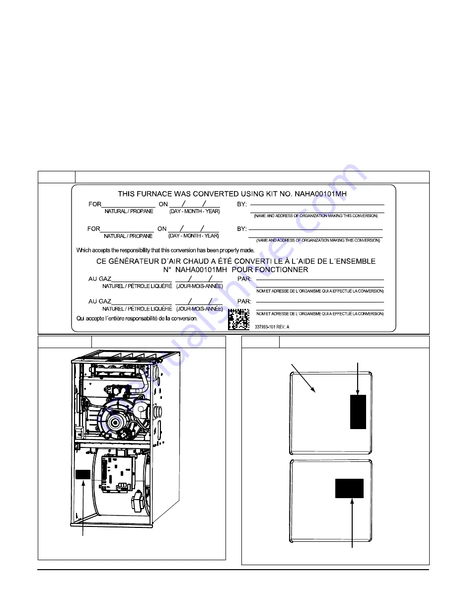
Procedure 3 — Label and Extra Parts Bag Attachment

NOTE

:  See 

Figure 6, Figure 7

 and 

Figure 8

 for label location.

1. Attach Conversion Responsibility Label (337993

101)

inside of main furnace door. (See 

Figure 7

) Date, name,

and address of organization making this conversion are

required. (See 

Figure 5

)

2. Attach Conversion Rating Plate Label (338299

101)

inside of lower left

hand side of controls compartment

(downflow) as shown in 

Figure 6

.

3. Attach Manufactured (Mobile) Home Installation Label

(322236

101) inside of main furnace door. (See

Figure 7

)

4. Attach adhesive pouch (337985

101) containing gas

orifices and Installation Instructions to front of main

furnace door or accessible furnace side. (See 

Figure 1

or 

Figure 8

)

5. Proceed to 

Section II

 or 

III

 for gas type modification and

Input  rate adjustment.

Figure 5

Conversion Responsibility Label

Figure 6

Conversion Rating Plate Label Location

FURNACE CONVERSION

RATING PLATE

REPRESENTATIVE DRAWING ONLY, SOME MODELS MAY VARY.

Figure 7

Installation & Responsibility Label Locations

RESPONSIBILITY LABEL

MANUFACTURED (MOBILE)

HOME INSTALLATION LABEL

INSIDE OF DOORS

REPRESENTATIVE DRAWING ONLY, SOME MODELS MAY VARY.

Summary of Contents for NAHA00101MH

Page 1: ...utions that may apply Follow all safety codes In the United States follow all safety codes including the current edition of the National Fuel Gas Code NFGC NFPA No 54 ANSI Z223 1 In Canada refer to the current edition of the National Standard of Canada Natural Gas and Propane Installation Codes NSCNGPIC CAN CSA B149 1 and 2 Wear safety glasses and work gloves Have a fire extinguisher available dur...

Page 2: ...l Gas to Propane SECTION III Conversion from Propane to Natural Gas SECTION I INITIAL KIT INSTALLATION Procedure 1 General A downflow furnace application is where furnace blower is located above combustion and controls section of furnace and conditioned air is discharged downwards Attach adhesive pouch containing literature packet and gas conversion parts to outside of main furnace door or accessi...

Page 3: ...SING IS NOT INSTALLED NOT SHOWN 1 Accessory floor base MUST be used Review floor base Installation Instructions before installation 2 Secure accessory floor base to structure using 5 16 in 8 mm lag screws 3 Fasten furnace to accessory floor base using No 10 self tapping screws through tabs on both sides of base two each side Procedure 2 Replace Gas Valve CAUTION UNIT OPERATION HAZARD Failure to fo...

Page 4: ...ctor harness from gas valve Disconnect wires from Hot Surface Igniter HSI and Flame Sensor See Figure 9 8 Support the manifold and remove the four 4 screws that secure the manifold assembly to the burner box and set aside 9 Note the location of the green yellow wire ground wire for re assembly later See Figure 3 10 Remove production gas valve from manifold assembly and discard valve NOTE Productio...

Page 5: ...Figure 8 for label location 1 Attach Conversion Responsibility Label 337993 101 inside of main furnace door See Figure 7 Date name and address of organization making this conversion are required See Figure 5 2 Attach Conversion Rating Plate Label 338299 101 inside of lower left hand side of controls compartment downflow as shown in Figure 6 3 Attach Manufactured Mobile Home Installation Label 3222...

Page 6: ...on furnace rating plate is for installations at altitudes up to 2000 ft 610 M In the U S A the input rating for altitudes above 2000 ft 610 M must be reduced by 2 percent for each 1000 ft 305 M above sea level In Canada the input rating must be derated by 5 percent for altitudes of 2000 ft to 4500 ft 610 M to 1372 M above sea level The Conversion Kit Rating Plate accounts for high altitude derate ...

Page 7: ... drill bit A11460 Figure 14 Igniter Position Back View 2 1 2 in 64 4 1 1 4 in 31 8 A11405 Figure 15 Igniter Position Side View A12392 2 in 2 5 mm 3 8 in 3 16 in 0 8 1 5 50 mm 9 6 mm 4 6 mm 3 32 in 1 32 3 64 in Figure 16 Convertible Gas Valve ON OFF SWITCH INLET PRESSURE TAP REGULATOR PLUNGER LP NAT CONVERTIBLE CAP GAS PRESSURE REGULATOR MANIFOLD PRESSURE TAP NAT LP BURNER ENCLOSURE PRESSURE REFERE...

Page 8: ...riels des blessures ou la mort 2 Apply pipe dope sparingly to the male threads of the 1 8 in black iron street elbow Install the street elbow into the gas valve inlet pressure tap Point the open end of the street elbow toward you 3 Apply pipe dope sparingly to the male threads of the 1 8 in brass street tee Install the male end of the street tee as shown in Figure 17 One opening on the street tee ...

Page 9: ...re 9 2 Align the orifices in the manifold assembly with the support rings on the end of the burner 3 Insert the orifices in the support rings of the burners Manifold mounting tabs should fit flush against the burner box NOTE If manifold does not fit flush against the burner box the burners are not fully seated forward Remove the manifold and check burner positioning in the burner box assembly 4 At...

Page 10: ...as valve switch to OFF position CHECK FURNACE AND MAKE ADJUSTMENTS 1 Be sure main gas and electric supplies to furnace are off 2 Remove 1 8 in 3 mm pipe plug from manifold pressure tap on downstream side of gas valve 3 Attach manometer to manifold pressure tap on gas valve See Figure 16 4 Turn gas supply manual shutoff valve to ON position 5 Turn furnace gas valve switch to ON position WARNING FIR...

Page 11: ...flamme vive Utilisez plutôt un savon fait specifiquement pour la détection des fuites de gaz pour verifier tous les connections Un incendie ou une explosion peut entrainer des dommages matériels des blessures ou la mort 18 Check pressure tap plug for gas leaks when main burners ignite 19 Check for correct burner flame 20 Observe unit operation through two complete heating cycles 21 See Sequence of...

Page 12: ...ed by manifold pressure and orifice size Furnace gas input rate on rating plate is for installations at altitudes up to 2000 ft 610 M In the U S A the input rating for altitudes above 2000 ft 610M must be reduced by 2 percent for each 1000 ft 305 M above sea level In Canada the input rating must be derated by 5 percent for altitudes of 2000 ft 610 M to 4500 ft 1372 M above sea level Furnace input ...

Page 13: ...the 1 8 in NPT pipe plug from the tee fitting on the Low Gas Pressure Switch 5 Remove the Low Gas Pressure Switch from fittings on gas valve and discard 6 Remove remaining fittings from gas valve and discard 7 Install manometer fitting to the open end of the brass street tee Or if installation is to be completed later apply pipe dope to inlet pressure plug from gas valve and install in open end of...

Page 14: ...s with an open flame Use a commercially available soap solution made specifically for the detection of leaks to check all connections A fire or explosion may result causing property damage personal injury or loss of life AVERTISSEMENT RISQUE D EXPLOSION ET D INCENDIE Le fait de ne pas suivre cet avertissement pourrait entraîner des dommages corporels et ou la mort Ne jamais examiner pour les fuite...

Page 15: ...c for gas meter test dial to complete one revolution e Refer to Table 4 for cu ft of gas per hr f Multiply gas rate cu ft hr X heating value Btu cu ft using natural gas heating value from local gas utility supplier g Fill in Conversion Responsibility Label 321102 101 located on inside of main furnace door Date name and address of organization making the conversion is required h Check for gas leaks...

Page 16: ...3 2 42 3 3 42 3 4 915 825 43 3 6 43 3 7 43 3 8 42 3 2 850 44 3 8 43 3 5 43 3 6 43 3 7 875 44 3 6 44 3 7 43 3 4 43 3 5 4000 900 44 3 4 44 3 5 44 3 7 44 3 8 1219 925 44 3 2 44 3 4 44 3 5 44 3 6 950 44 3 1 44 3 2 44 3 3 44 3 4 750 42 3 3 42 3 4 42 3 5 42 3 6 4001 775 43 3 7 43 3 8 42 3 3 42 3 4 1220 800 43 3 5 43 3 6 43 3 7 43 3 8 825 44 3 8 43 3 4 43 3 5 43 3 6 850 44 3 5 44 3 7 44 3 8 43 3 4 5000 8...

Page 17: ... 3 3 42 3 4 2134 700 43 3 5 43 3 7 43 3 8 42 3 2 725 44 3 8 43 3 4 43 3 5 43 3 6 750 44 3 5 44 3 7 44 3 8 43 3 4 8000 775 44 3 3 44 3 4 44 3 5 44 3 7 2438 800 44 3 1 44 3 2 44 3 3 44 3 4 825 44 2 9 44 3 0 44 3 1 44 3 2 625 42 3 4 42 3 5 42 3 6 42 3 7 8001 650 43 3 8 42 3 2 42 3 3 42 3 4 2439 675 43 3 5 43 3 6 43 3 7 42 3 2 700 44 3 7 43 3 4 43 3 5 43 3 6 725 44 3 5 44 3 6 44 3 7 44 3 8 9000 750 44...

Page 18: ... 23 157 313 783 66 54 109 273 24 150 300 750 68 53 106 265 25 144 288 720 70 51 103 257 26 138 277 692 72 50 100 250 27 133 267 667 74 48 97 243 28 129 257 643 76 47 95 237 29 124 248 621 78 46 92 231 30 120 240 600 80 45 90 225 31 116 232 581 82 44 88 220 32 113 225 563 84 43 86 214 33 109 218 545 86 42 84 209 34 106 212 529 88 41 82 205 35 103 206 514 90 40 80 200 36 100 200 500 92 39 78 196 37 ...

Reviews: