6
443 06 4002 00
Specifications subject to change without notice.
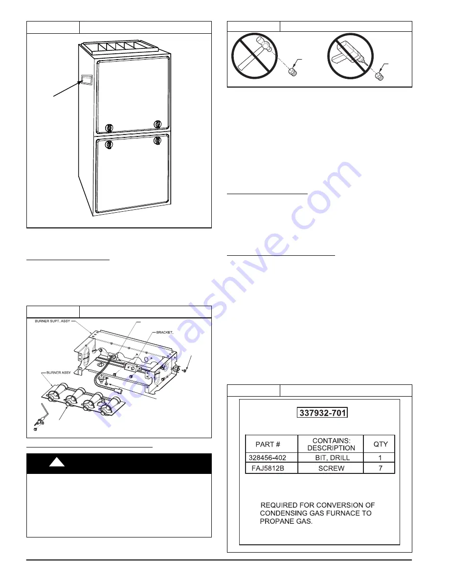
Figure 8
Label Locations
IMPORT
ANT
THIS BAG WIT
H
INSTR
UCTION
S
ENCLOS
ED M
UST
BE A
TTACH
ED T
O
FURN
ACE
ADHESIVE POUCH
REPRESENTATIVE DRAWING ONLY, SOME MODELS MAY VARY.
SECTION II: CONVERSION FROM NATURAL
GAS TO PROPANE
BURNER REMOVAL
1. Slide one
−
piece burner assembly out of slots on sides of
burner box.
2. Remove the flame sensor from the burner assembly.
3. Remove the natural gas orifices from the manifold and
discard.
Figure 9
Burner Assembly
FLAME SENSOR
(BELOW BURNER)
FLAME ROLL-OUT
SWITCH
FLAME ROLL-OUT
SWITCH
IGNITER
IGNITER
A11226
ORIFICE SELECTION/DERATE
!
WARNING
FIRE AND FURNACE DAMAGE HAZARD
Failure to follow this warning could result in personal injury,
death, property damage and/or unit damage.
DO NOT redrill orifices. Improper drilling (burrs, out
−
of
−
round
holes, etc.) can cause excessive burner noise and
misdirection of burner flames. This can result in flame
impingement of burners and heat exchangers causing
failures.
Figure 10
Burner Orifice
BURNER
ORIFICE
BURNER
ORIFICE
A96249
Refer to conversion kit rating plate 338298
−
101 to determine
main burner orifice size. (See
Figure 12
)
Furnace gas input rate on furnace rating plate is for installations
at altitudes up to 2000 ft. (610 M).
In the U.S.A., the input rating for altitudes above 2000 ft. (610
M) must be reduced by 2 percent for each 1000 ft. (305 M)
above sea level.
In Canada
,
the input rating must be derated by 5 percent for
altitudes of 2000 ft. to 4500 ft. (610 M to 1372 M) above sea
level.
The Conversion Kit Rating Plate accounts for high altitude
derate.
INSTALL ORIFICES
1. Install main burner orifices. Do not use Teflon tape.
Finger
−
tighten orifices at least one full turn to prevent
cross
−
threading, then tighten with wrench.
2. There are enough orifices in each kit for largest furnace.
Discard extra orifices.
NOTE
: DO NOT reinstall the manifold at this time.
INSTALL MIXER SCREWS
NOTE
: There is a set of mixer screws. Use the parts in the bag
marked “REQUIRED FOR THE CONVERSION OF
CONDENSING GAS FURNACES TO PROPANE GAS”
1. See
Figure 11
to verify you have the correct set of mixer
screws.
2. Locate the dimple on each burner venturi tube.
3. If you cannot locate the dimple, refer to
Figure 13
for
location of the mixer screw.
4. Drill a 7/64
−
in (2.8 mm) hole (supplied in kit) in each
dimple.
5. Install a mixer screw in each drilled hole drilling as
straight as possible (i.e. in the center of the gas flow
stream as well as perpendicular to the gas flow stream).
6. The screw head should be flush with the top of the
burner venturi.
Figure 11
Gas Conversion Kit
A11294


