background image

Printed in U.S.A.

462 01 2001 01

01--28--08

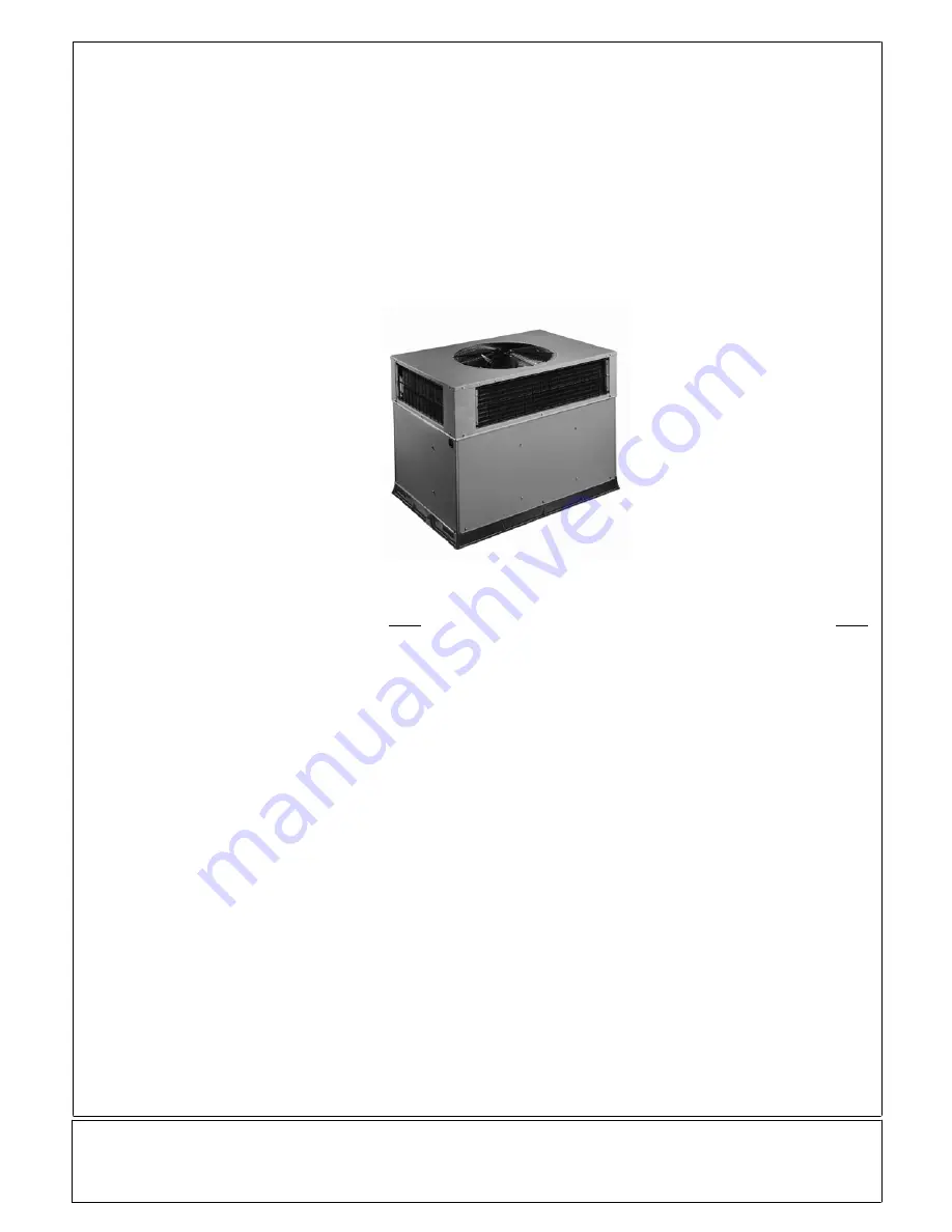
PACKAGED GAS/ELECTRIC UNIT

Installation Instructions

PGN4 Series

International Comfort Products, LLC

Lewisburg, TN. 37091

TABLE OF CONTENTS

Page

SAFE INSTALLATION REQUIREMENTS

2

. . . . . . . .

INTRODUCTION

3

. . . . . . . . . . . . . . . . . . . . . . . . . . . . .

RECEIVING AND INSTALLATION

3

. . . . . . . . . . . . . . .

Check Equipment

3

. . . . . . . . . . . . . . . . . . . . . . . . . . .

Provide Unit Support

3

. . . . . . . . . . . . . . . . . . . . . . . .

Field Fabricate Ductwork

3

. . . . . . . . . . . . . . . . . . . .

Dimensions

4 -- 5

. . . . . . . . . . . . . . . . . . . . . . . . . . . . .

Provide Clearances

6

. . . . . . . . . . . . . . . . . . . . . . . . .

Rig and Place Unit

6 -- 7

. . . . . . . . . . . . . . . . . . . . . . .

Connect Condensate Drain

7

. . . . . . . . . . . . . . . . . .

Install Flue Hood

7 -- 8

. . . . . . . . . . . . . . . . . . . . . . . .

Install Gas Piping

8

. . . . . . . . . . . . . . . . . . . . . . . . . . .

Install Duct Connections

9 -- 10

. . . . . . . . . . . . . . . .

Install Electrical Connections

10 -- 13

. . . . . . . . . . .

PRE--START--UP

14

. . . . . . . . . . . . . . . . . . . . . . . . . . . .

START--UP

14

. . . . . . . . . . . . . . . . . . . . . . . . . . . . . . . . . .

Check for Refrigerant Leaks

14

. . . . . . . . . . . . . . . . .

Start--Up Heating & Make Adjustments

14 -- 15

. .

Gas Input

15

. . . . . . . . . . . . . . . . . . . . . . . . . . . . . . .

Measure Gas Flow

16

. . . . . . . . . . . . . . . . . . . . . . .

Airflow and Temperature Rise

17

. . . . . . . . . . . . . .

LED Monitor

17

. . . . . . . . . . . . . . . . . . . . . . . . . . . . .

Sequence of Operation

17

. . . . . . . . . . . . . . . . . . .

Start--Up Cooling & Make Adjustments

18

. . . . . . .

R--410A Charge

18 -- 19

. . . . . . . . . . . . . . . . . . . . .

Airflow

20

. . . . . . . . . . . . . . . . . . . . . . . . . . . . . . . . . .

Sequence of Operation

20

. . . . . . . . . . . . . . . . . . .

Page

MAINTENANCE

21

. . . . . . . . . . . . . . . . . . . . . . . . . . . . .

Air Filter

21

. . . . . . . . . . . . . . . . . . . . . . . . . . . . . . . . . .

Indoor Blower and Motor

21

. . . . . . . . . . . . . . . . . . . .

Flue Gas Passageways

22

. . . . . . . . . . . . . . . . . . . .

Induced Draft (Combustion Air) Blower

22

. . . . . . .

Limit Switch

22

. . . . . . . . . . . . . . . . . . . . . . . . . . . . . . .

Burner Ignition

22

. . . . . . . . . . . . . . . . . . . . . . . . . . . .

Main Burners

22

. . . . . . . . . . . . . . . . . . . . . . . . . . . . . .

Outdoor & Indoor Coil, Condensate Drain Pan 22

.

Outdoor Fan

23 -- 24

. . . . . . . . . . . . . . . . . . . . . . . . .

Electrical Controls and Wiring

24

. . . . . . . . . . . . . . .

Refrigeration Circuit

24

. . . . . . . . . . . . . . . . . . . . . . . .

Gas Input

24

. . . . . . . . . . . . . . . . . . . . . . . . . . . . . . . . .

Evaporator Airflow

24

. . . . . . . . . . . . . . . . . . . . . . . . .

R--410A Items

24 -- 25

. . . . . . . . . . . . . . . . . . . . . . . .

AIRFLOW CHART

26 -- 29

. . . . . . . . . . . . . . . . . . . . . .

COOLING TROUBLESHOOTING GUIDE

30

. . . . . . .

HEATING TROUBLESHOOTING GUIDE

31

. . . . . . .

LED ERROR CODES GUIDE

32

. . . . . . . . . . . . . . . . . .

R--410A QUICK REFERENCE GUIDE

33

. . . . . . . . . .

CHECKLIST FORM

34

. . . . . . . . . . . . . . . . . . . . . . . . . .

Summary of Contents for PGN4 Series

Page 1: ...igerant Leaks 14 Start Up Heating Make Adjustments 14 15 Gas Input 15 Measure Gas Flow 16 Airflow and Temperature Rise 17 LED Monitor 17 Sequence of Operation 17 Start Up Cooling Make Adjustments 18 R...

Page 2: ...signifies a hazard which could result in serious injury or death CAUTION is used to identify unsafe practices which may result in minor personal injury or product and property damage NOTE is used to h...

Page 3: ...m This is necessary for unit drain to function properly Refer to accessory roof curb installation instructions for additional information as required Slab Mount Place the unit on a solid level concret...

Page 4: ...NIT HEIGHT IN MM A CENTER OF GRAVITY IN MM lb kg X Y Z 24 208 230 1 60 208 230 3 60 307 139 3 37 940 23 6 599 4 15 8 401 3 15 7 398 8 30 208 230 1 60 208 230 3 60 319 144 7 37 940 23 6 599 4 15 8 401...

Page 5: ...EIGHT IN MM A CENTER OF GRAVITY IN MM lb kg X Y Z 42 208 230 1 60 208 230 3 60 435 197 3 46 98 1193 25 5 647 7 21 0 533 17 6 447 48 208 230 1 60 208 230 3 60 453 205 5 46 98 1193 25 7 652 8 21 8 553 7...

Page 6: ...is engineered and designed to be installed only on Small Packaged Products This bracket is to be used to rig lift a Small Packaged Product onto roofs or other elevated structures Prior to initial use...

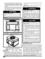
Page 7: ...ugh the base on the evaporator coil access side See Figures 3 4 for location Condensate water can be drained directly onto the roof in rooftop installations where permitted or onto a gravel apron in g...

Page 8: ...t on the unit gas valve For natural gas applications the gas pressure at unit gas connection must not be less than 4 0 inches water column or greater than 13 inches water column while the unit is oper...

Page 9: ...size ductwork supply air registers and return air grilles according to American Society of Heating Refrigeration and Air Conditioning Engineers ASHRAE recommendations 3 Use flexible transition betwee...

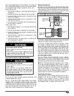
Page 10: ...rds Institute National Fire Protection Association latest edition in Canada Canadian Electrical Code CSA C22 1 and local electrical codes WARNING UNIT COMPONENT DAMAGE HAZARD Failure to follow this ca...

Page 11: ...s measured along the control voltage wires use no 16 AWG color coded insulated 35_C minimum wires Standard Connection Remove knockout hole located in the flue panel adjacent to the control access pane...

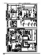
Page 12: ...12 FIGURE 11 208 230 1 60 WIRING DIAGRAM ON MODEL SIZES 24 36 MODEL SIZES 42 60...

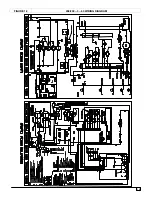
Page 13: ...13 FIGURE 12 208 230 3 60 WIRING DIAGRAM ON MODEL SIZES 24 36 MODEL SIZES 42 60...

Page 14: ...s do not touch refrigerant tubing or sharp sheet metal edges f Inspect coil fins If damaged during shipping and handling carefully straighten fins with a fin comb FIRE EXPLOSION HAZARD Failure to foll...

Page 15: ...ing value of 2500 Btu ft3 at 1 5 specific gravity When the gas supply being used has a different heating value or specific gravity refer to national and local codes or contact your distributor to dete...

Page 16: ...ze of test dial is 1 ft3 one revolution takes 32 seconds and the heating value of the gas is 1050 BTU ft3 Proceed as follows 1 32 seconds to complete one revolution 2 3600 32 112 5 3 112 5 x 1 112 5 f...

Page 17: ...3 8 10 0 11 0 When a unit is converted to Propane different size orifices must be used See separate natural to Propane conversion kit instructions Based on altitudes from sea level to 2000 feet above...

Page 18: ...not required unless the unit is suspected of not having the proper R 410A charge The charging label and the tables shown refer to system temperatures and pressures in cooling mode only A refrigerant c...

Page 19: ...414 119 114 109 104 99 94 2854 48 46 43 40 37 34 424 121 116 111 106 101 96 2923 49 47 44 41 38 35 434 123 118 113 108 103 98 2992 50 48 45 42 39 36 444 124 119 114 109 104 99 3061 51 48 46 43 40 37 4...

Page 20: ...ing Remove the current speed tap wire from the COOL terminal on the Interface Fan Board IFB see Figure 16 and place vinyl cap over the connector on the wire Connect the desired speed tap wire to the C...

Page 21: ...ing season Service when necessary 5 Ensure electric wires are not in contact with refrigerant tubing or sharp metal edges 6 Check and inspect heating section before each heating season Clean and adjus...

Page 22: ...curs unit may be reset by either momentarily interrupting power supply to unit or by turning selector switch to OFF position at the thermostat Main Burners At the beginning of each heating season insp...

Page 23: ...to turn off the electrical power to the unit Remove access panel to locate all the electrical controls and wiring Check all electrical connections for tightness Tighten all screw connections If any s...

Page 24: ...650 psig High pressure may be caused by a dirty outdoor coil failed fan motor or outdoor air recirculation To check switch 1 Turn off all power to unit 2 Disconnect leads on switch 3 Apply ohm meter l...

Page 25: ...n offs through the louvered openings in the unit base 3 Perform required service 4 Remove and dispose of any oil contaminated material per local codes Liquid Line Filter Drier This filter drier is spe...

Page 26: ...NA NA Heating Rise oC 22 23 25 27 29 NA NA NA NA High1 Black CFM 1202 1140 1082 1015 961 881 810 732 631 Heating Rise oF 37 39 41 44 46 50 55 NA NA Heating Rise oC 21 22 23 24 26 28 30 NA NA PGN430040...

Page 27: ...26 27 28 29 30 31 33 High1 Black CFM 1599 1553 1505 1460 1410 1361 1310 1262 1203 Heating Rise oF 43 44 45 47 48 50 52 54 57 Heating Rise oC 24 24 25 26 27 28 29 30 31 PGN442060 25 55 F 14 31 C Low1 B...

Page 28: ...3 23 23 24 24 25 26 26 27 High Black CFM 2461 2409 2339 2286 2192 2140 2062 1968 1874 Heating Rise oF 35 36 37 38 40 41 42 44 46 Heating Rise oC 20 20 21 21 22 23 23 25 26 PGN448130 35 65 F 19 36 C Lo...

Page 29: ...52 54 56 57 59 61 63 NA Heating Rise oC 28 29 30 31 32 33 34 35 NA Med High1 Orange CFM 2055 2008 1958 1927 1900 1768 1685 1581 1458 Heating Rise oF 47 48 49 50 51 54 57 61 NA Heating Rise oC 26 27 27...

Page 30: ...oltage Determine cause and correct Blocked outdoor coil Determine cause and correct Defective run start capacitor Determine cause and replace Faulty outdoor fan motor or capacitor Replace Restriction...

Page 31: ...for any gas to dissipate before attempting to light unit 2 Check gas valve Inadequate heating Dirty air filter Clean or replace filter as necessary Gas input to furnace too low Check gas pressure at m...

Page 32: ...gas Induced draft motor fault LED 6 flashes Open pressure switch Verify wiring connections to pressure switch and inducer motor Verify pressure switch hose is tightly connected to both inducer housing...

Page 33: ...detect HFC refrigerant R 410A as with other HFC refrigerants is only compatible with POE oils Vacuum pumps will not remove moisture from oil Do not use liquid line filter driers with rated working pr...

Page 34: ...orifice no rubs and set screw tightness 3 Start Up Electrical Supply Voltage measured Compressor Amps measured Indoor evaporator motor amps Temperatures Outdoor condenser air temperature dry bulb Indo...

Reviews: