18
513 01 3222 00
Specifications are subject to change without notice.
C14225
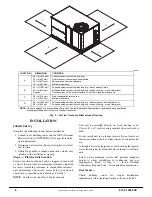
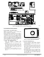
Fig. 28 -- EconoMi$er X W7220 Controller Wiring Diagram
Hot Gas Re--Heat Control Connections
Hot Gas Re--Heat -- Space RH Controller —
NOTE
: Hot Gas Re--Heat is a factory installed option
which is available for 072 models only.
The Hot Gas Re--Heat dehumidification system requires a
field--supplied and --installed space relative humidity
control device. This device may be a separate humidistat
control (contact closes on rise in space RH above control
setpoint) or a combination thermostat--humidistat control
device with isolated contact set for dehumidification
control. The humidistat is normally used in applications
where a temperature control is already provided.
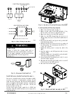
To connect a field--supplied humidistat:
1. Route
the
humidistat
2--conductor
cable
(field--supplied) through the hole provided in the unit
corner post.
2. Feed wires through the raceway built into the corner
post (see Fig. 22) to the 24--v barrier located on the
left side of the control box. The raceway provides the
UL--required clearance between high--voltage and
low--voltage wiring.
3. Use wire nuts to connect humidistat cable to two
PINK leads in the low–voltage wiring as shown in
Fig. 30.
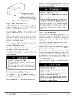
% RELATIVE HUMIDITY
C09295I
Fig. 29 -- Accessory Field--Installed Humidistat
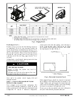
To connect the Thermidistat device:
1. Route the Thermostat multi--conductor thermostat
cable (field--supplied) through the hole provided in
the unit corner post.
2. Feed wires through the raceway build into the corner
post (see Fig. 22) to the 24--v barrier located on the
left side of the control box. The raceway provides the
UL--required clearance between high--voltage and
low--voltage wiring.
3. The Thermostat has dry contacts at terminals D1 and
D2 for dehumidification operation (see Fig. 31). The
dry contacts must be wired between CTB terminal R
and the PINK lead to the LTLO switch with
field--supplied wire nuts.


