1.0
HARDWARE INITIALIZATION
1.1
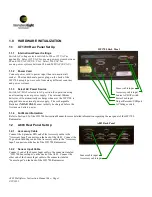
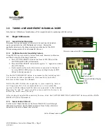
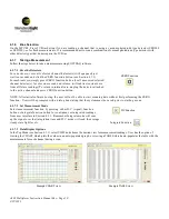
ILT1700 Rear Panel Set Up
1.1.1
International Power Settings
Switch AC voltage selector switch to 220 or 115 VAC as
applicable. Select 115 VAC for use on power systems between
90 and 130 VAC (JP, US, CA). Select 230 VAC for
use on power systems between 180 and 260 VAC (EC, AU).
1.1.2
Power Cord
Connect power cord to power input then into main wall
socket. The standard male power plug on the back of the
ILT1700 accepts power cords from many different countries
and power systems.
1.1.3
Select AC Power Source
Switch AC / BAT selector to AC position for operation using
an alternating current power supply. The internal lithium
batteries will automatically recharge whenever the ILT1700 is
plugged into an external power supply. The rechargeable
Batteries (NICAD ONLY) must initially be charged before the
first use on battery power.
1.1.4
For More Information
Refer to Section 2.2 of the ILT1700 Instruction Manual for more detailed information regarding the rear panel of the ILT1700
Radiometer.
1.2
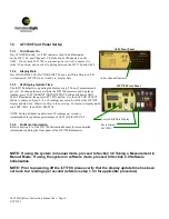
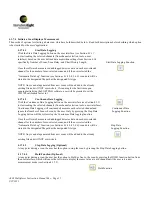
A803 Rear Panel Set Up
1.2.1
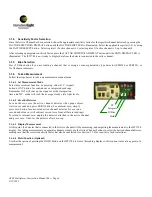
Accessory Cable
Connect the 6-pin mini DIN end of the Accessory cable to the
“Accessory Input” connector on the back of the A803. Connect the
24 position CardEdge end of the Accessory cable to the “Accessory
Input” connector on the back of the ILT1700 Radiometer.
1.2.2
Sensor Input Cable
Connect 1 end of the Sensor Input cable to the connector labeled
“ILT1700 Sensor Input” on the back of the A803. Connect the
other end of the Sensor Input cable to the connector labeled
“Sensor Input” on the back of the ILT1700 Radiometer.
A803 Multiplexer Instruction Manual Rev -
Page 1
9/22/
2011
AC Voltage switch
Power Cord input
Source AC/BAT switch
Output Recorder/USB port
Accessory cable input
Sensor cable input
Sensor cable input
Accessory cable input
A803 Back Panel
ILT1700 Back Panel


