IRDC3898-P3V3
8/15/2013
Confidential
This evaluation board is a preliminary version meant for the engineering evaluation of the IR3898.
Based on the results of the continuing evaluation, this board can evolve and change without notice
14
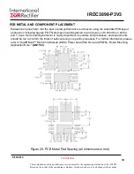
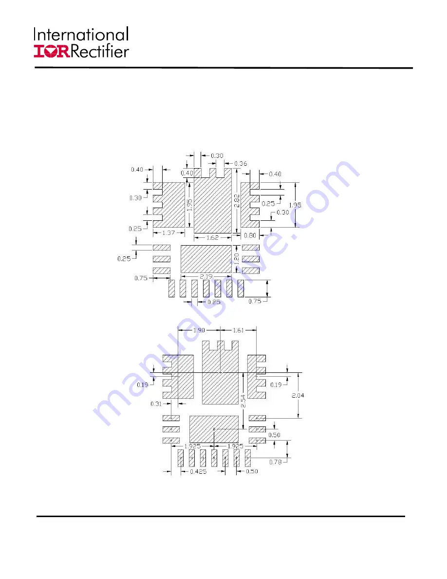
PCB METAL AND COMPONENT PLACEMENT
Evaluations have shown that the best overall performance is achieved using the substrate/PCB layout
as shown in following figures. PQFN devices should be placed to an accuracy of 0.050mm on both X
and Y axes. Self-centering behavior is highly dependent on solders and processes, and experiments
should be run to confirm the limits of self-centering on specific processes.
For further information, please
refer to “SupIRBuck™ Multi-Chip Module (MCM) Power Quad Flat No-Lead (PQFN) Board Mounting
Application Note
.” (AN1132)
Figure 20: PCB Metal Pad Spacing (all dimensions in mm)

