Section 9, Installing the Distribution Module
•
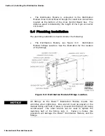
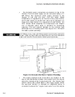
The Domestic water connections are located on top of the
module. The Cold water supply can be connected using a ½”
NPT fitting. The maximum water supply pressure to the
module is 150 PSI (10 bar). The Hot water Outlet
temperature is regulated by an internal mixing valve factory
set at 120F (49°C). If needed this valve can be adjusted in a
range from 100F (38°C) to a maximum of 145F (63°C). For
more details about adjusting the temperature see chapter
9.9. A domestic water drain is provided for winterizing
purposes. This will prevent damage to the internal heat
exchanger due to freezing water. See Figure 9-4: Domestic
Hot water system plumbing.
All fittings, hose, tube and fitting sealant involving the domestic
water must be food safe and approved for use with domestic
water and rated for the domestic water system pressure.
WARNING
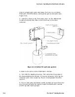
Figure 9-4 Domestic Hot Water System Plumbing.
•
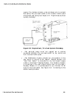
The engine heat/pre-heat connections are located on the
side of the distribution module. Hot coolant from the engine
enters the module at the “engine heat inlet”. The “engine heat
outlet” returns the coolant back to the engine supply. When
the pre-heat function is installed an additional pump is
connected between the “engine heat outlet” and the engine
9-4
The Oasis™ Heating Module
Summary of Contents for Diesel and AC Heating System for Recreational Vehicles and Yachts
Page 14: ...Section 1 Overview 1 8 The Oasis Heating Module...
Page 20: ...Section 2 Mounting the Oasis Heating Module 2 6 The Oasis Heating Module...
Page 28: ...Section 3 Installing the Exhaust System 3 8 The Oasis Heating Module...
Page 32: ...Section 4 Installing the Fuel System 4 4 The Oasis Heating Module...
Page 41: ......
Page 48: ...Section 7 Plumbing the System 7 6 The Oasis Heating Module...
Page 73: ......
Page 74: ...9...
Page 75: ...6 6 6 6 7K 8 0 7 4 7 4 7 8 9 7 8 9 7 8 9 7 8 9 D B 15C 8 D D H D 13 C 8 B B EC 8 D...
Page 76: ...Section 9 Installing the Distribution Module 9 14 The Oasis Heating Module...


