background image

Section 9, Installing the Distribution Module  


9-14 


The Oasis™ Heating Module 

Summary of Contents for Diesel and AC Heating System for Recreational Vehicles and Yachts

Page 1: ...OASIS Hea ing Module t Installation and Operating Manual Diesel and AC Heating System for Recreational Vehicles and Yachts CSA TIL R 17 ANSI UL307A CAN CSA C22 2 No 165...

Page 2: ...t com All rights reserved No part of this manual may be reproduced or transmitted in any form by any means electronic or mechanical including photocopying and recording information storage retrieval o...

Page 3: ...2 2 2 3 Your Mounting Location 2 2 2 4 What NOT to Do 2 4 2 5 Procedure 2 4 Section 3 Installing the Exhaust System 3 1 3 1 Before You Begin 3 1 3 2 Mounting Location 3 1 Recommended Exhaust Outlet L...

Page 4: ...Installation 7 1 7 3 What NOT to Do 7 4 7 4 Installation Procedure 7 4 Section 8 Operating the Oasis Heating Module 8 1 8 1 Features of your Oasis Heating Module 8 1 8 2 Your Heating Module Model 8 2...

Page 5: ...DM 12 optional 9 1 9 1 Installing your Distribution Module optional 9 1 9 2 Selecting the Module Location 9 1 9 3 Selecting the Distribution Module Zone Box Location 9 2 9 4 Plumbing Installation 9 3...

Page 6: ...g Heater Hose consult ITR for alternative methods and products 7 5 Figure 8 1 Oasis Heating Module 8 3 Figure 8 2 Heating Module Main Control Panel 8 4 Figure 8 3 Remote Operating Panel 8 7 Figure 8 4...

Page 7: ...ed only for installation into Recreational Vehicles Manufactured Homes and Mobile housing Section 1 NOTICE This section covers critical information you need to know before beginning the installation i...

Page 8: ...ons To ensure that you and or your customers receive satisfactory results and enjoy a warm comfortable environment To ensure a trouble free installation a successful inspection and testing process and...

Page 9: ...ution pumps the Oasis Heating Module has the ability to circulate the coolant fluid to all space heating areas It can also provide a supply of domestic hot water using the integral heat exchanger in t...

Page 10: ...dule Remote Operating Panel with ON OFF switch for the diesel burner AC elements and engine heat if installed Heating Module Control Panel with buttons for Power Bypass Reset and indicator LED s for o...

Page 11: ...the installation are Pay attention to the notices of Danger Warning Caution and Notice in this manual Mounting location restrictions for the Oasis Heating Module optional Distribution Module and exhau...

Page 12: ...ent and tools to install the heating system not supplied This list does not include optional equipment and accessories Standard tools normally available in a well equipped shop Approved fasteners for...

Page 13: ...alled according to standard practices RVIA or ABYC standards and the recommendations of this Installation and Operating Manual the Oasis Heating Module should be test operated for inspection purposes...

Page 14: ...Section 1 Overview 1 8 The Oasis Heating Module...

Page 15: ...s Heating Module weight when full 160 lbs Ventilation requirements Exhaust outlet location and maximum acceptable length Thru hull location and waterline yachts Potential for vibration and jarring Len...

Page 16: ...tified by locating the serial number label on the outside case of the Oasis Heating Module The serial number identifies the model type through the first series of letters and numbers The types of Oasi...

Page 17: ...rackets Mount the unit with the front panel side facing out and accessible Facing out simplifies installation and maintenance Oasis Heating Module must be mounted horizontal and level using eight 1 4...

Page 18: ...t the exhaust tubing can be properly and safely routed to the outside The maximum exhaust run for the system is 12 2 4 What NOT to Do Don t mount the Oasis Heating Module in the rear of the coach or y...

Page 19: ...Section 2 Mounting the Oasis Heating Module Figure 2 2 Module Mounting Brackets International Thermal Research 2 5...

Page 20: ...Section 2 Mounting the Oasis Heating Module 2 6 The Oasis Heating Module...

Page 21: ...the unit will infiltrate the living areas Never place any exhaust parts close to combustible material or through a combustible wall or ceiling without fireproof protection The exhaust can reach high t...

Page 22: ...f the dual exhaust air intake thru hull is used ensure that the air intake is placed between 10 o clock and 2 o clock and also goose necked to avoid water ingestion see Figure 3 3 The Exhaust Goose Ne...

Page 23: ...installed length The exhaust and Oasis Heating Module connection point must use appropriate clamps and sealing compound to ensure that the connections are tight and leak free The Oasis Heating Module...

Page 24: ...they apply firm even pressure In a coach install an exhaust collar on the exhaust pipe to isolate the pipe from the coach frame This reduces vibration and noise and protects the coach from the effect...

Page 25: ...ssible to facilitate air flow See figure 3 1 Installation of the air intake adapter to the side of the RV Locate a suitable location to mount the air intake adapter Drill a 2 hole through the side wal...

Page 26: ...Section 3 Installing the Exhaust System Figure 3 1 Installing the Exhaust System Bottom Exhaust Figure 3 2 The Exhaust Hole Location Mounting Template 3 6 The Oasis Heating Module...

Page 27: ...Section 3 Installing the Exhaust System Figure 3 3 The Exhaust Goose Neck configuration International Thermal Research 3 7...

Page 28: ...Section 3 Installing the Exhaust System 3 8 The Oasis Heating Module...

Page 29: ...ot rated for use in an explosive environment Never share the fuel supply to the Oasis Heating Module with any other fuel burning device WARNING 4 2 Fuel System Installation The fuel pump in the Oasis...

Page 30: ...UTION All fuel line connection points and hoses must use suitable clamps and or sealant and must be checked for leaks on the initial installation and also periodically as part of normal maintenance A...

Page 31: ...te the fuel system installation 1 Install the inline fuel filter The optimal location is on a compartment wall next to the Oasis Heating Module inline between the fuel tank and the Oasis Heating Modul...

Page 32: ...Section 4 Installing the Fuel System 4 4 The Oasis Heating Module...

Page 33: ...turns on the fan when the water running through it reaches 120 F 49 C The Defrost Heater provides up to 28 000 BTU h and uses a three speed fan 200 275 450 cfm 40 55 100 watts Note A limited number of...

Page 34: ...nt There must be an input and output vent for each fan unit Features ITR heater fans can be supplied with a built in aquastat which prevents fan operation until the system has reached minimum operatin...

Page 35: ...t supplied but which can be purchased separately Thermostats thermostats can be installed in the interior Air Outlet Vents covers that are installed flush with the wall to vent heat for the installed...

Page 36: ...ations Carefully choose the mounting locations of your fans Locate the fans to evenly heat the zone Provision must be made to protect water lines from freezing ITR can suggest optimal fan locations if...

Page 37: ...n for the thermostat as well as any fan speed switches You will wire these up to the Zone Control Board in Section 9 Installing the Distribution Module 4 The zone control board can control up to 5 zon...

Page 38: ...Section 5 Installing Fan Heaters Figure 5 2 Mounting a Spacesaver Fan Figure 5 3 Installing a Relay for Additional Fan Amperage 5 6 The Oasis Heating Module...

Page 39: ...National Electrical Code ANSI NFPA 70 Section 6 WARNING 6 2 12 VDC The following apply to the 12 VDC connections for the Oasis Heating Module There is one paired set of 12 VDC electrical connections o...

Page 40: ...ing Module The secondary set of wires is connected to the other AC element If only one AC circuit breaker is available you must connect to the primary wire set only Once the connections are completed...

Page 41: ......

Page 42: ...is charging Do not wire the Oasis Heating Module through a disconnect that is used as a normal shut down of the DC system NOTICE Doing either will severely damage the Oasis Heating Module because it f...

Page 43: ...on of the Oasis Heating Module follow all recommendations for properly installing the plumbing system Any deviations from these must be approved in advance by ITR The Oasis Heating Module when attache...

Page 44: ...and output connections must be heavy duty heater hose minimum 3 4 I D or 5 8 PEX All fittings on the Oasis Heating Module require two wrenches when tightening One wrench must be placed on the tank fi...

Page 45: ...s adequate through the Oasis Heating Module and the system An indication of inadequate flow is when the Oasis Heating Module is running and up to normal operating temperature the difference between th...

Page 46: ...olvents which may cause it to soften and swell If there is any risk that solvents may contact the hose insert it into PVC plastic tubing for protection 7 4 Installation Procedure To install and connec...

Page 47: ...the Oasis Heating Module through the filler neck with the recommended propylene glycol water anti freeze solution and bleed all trapped air Do not operate the Oasis Heating Module until the proper wat...

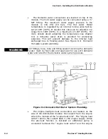
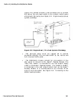
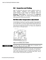
Page 48: ...Section 7 Plumbing the System 7 6 The Oasis Heating Module...

Page 49: ...When used with the Distribution Module and its integral distribution pumps the Oasis Heating Module has the ability to circulate the coolant fluid to all space heating areas It can also provide a supp...

Page 50: ...h buttons for Power Bypass Reset and indicator LED s for operational and diagnostic information Available with the Optional Distribution Module Three distribution pumps one heat exchanger for heating...

Page 51: ...erating Instructions for the Oasis Heating Module The Oasis Heating Module must be installed and connections made in accordance with the recommendations in the Installation and Operating Manual prior...

Page 52: ...be left ON during any period where heat is requested When the Oasis Heating Module is shut down for any extended period or the season it is recommended that the power switch be turned OFF Figure 8 2...

Page 53: ...is again achieved If the burner switch on the remote panel is turned OFF the burner stops and the Oasis Heating Module enters a two minute cool down stage prior to completely shutting down Activating...

Page 54: ...aquastat that prevents the cabin fan from blowing cold air Once the room temperature has reached the temperature called for by the thermostat the cabin fan will turn off 8 7 Activating the Domestic H...

Page 55: ...to the normal operating temperature Turn the burner switch on the Remote Operating Panel to the ON position The Oasis Heating Module will come up to the set operating temperature range and will cycle...

Page 56: ...tional controls the ON OFF of the engine pre heat pump not included However the engine pre heat pump not included will not function unless the coolant in the Oasis Heating Module has achieved a preset...

Page 57: ...ns ON OFF power Bypass and Reset In addition it contains nine LED s indicating Power AC Heat Compressor Fuel Pump Combustion Fan Igniter Flame Out Voltage and Low Water Power Button The power button t...

Page 58: ...d turns ON when a voltage fault has been detected Low Water Red The Low Water LED red turns ON when a low coolant level in the Oasis Heating Module has been detected 8 11 Functions of the Distribution...

Page 59: ...Section 8 Operating the Heating Module Figure 8 4 Zone Control Panel Power LED Green The power LED turns ON when the power to the Distribution Module Zone Control Board is ON...

Page 60: ...rm the service tune up It is recommended that the dealer be contacted for this service or if not available contact ITR for information on service resources As a general guide the regular maintenance i...

Page 61: ...using a proper mixture of anti freeze and water Use only a non toxic propylene glycol based coolant with additives generally recognized as safe GRAS by the FDA in the Oasis Heating Module and Distrib...

Page 62: ...placed in the one or two element position AC Heat LED lit on Remote Operating Panel AC immersion elements circuit breakers tripped Burner Starts but Flame Faults Fuel supply present and adequate Air...

Page 63: ...kmanship is essential to the proper function and life of your module as well as protecting your warranty 9 2 Selecting the Module Location The installation should consider the following Mounting locat...

Page 64: ...3 Selecting the Distribution Module Zone Box Location Mount the Distribution Module Zone Box containing the Zone Control Board vertically close to the Distribution Module Allow sufficient room to acce...

Page 65: ...ribution Module see Figure 9 3 Distribution Module Fittings Location See the illustration for the location of the fittings Figure 9 3 Distribution Module Fittings Location All fittings on the Oasis Di...

Page 66: ...oses This will prevent damage to the internal heat exchanger due to freezing water See Figure 9 4 Domestic Hot water system plumbing All fittings hose tube and fitting sealant involving the domestic w...

Page 67: ...t accidental shorting The pre heat switch on the remote will turn on power to the wires The Distribution module contains two connections on the side panel to connect to the Oasis Heating Module The In...

Page 68: ...two separate heating loops labeled Heating loop 1 supply and Heating loop 2 supply Each loop can contain several fans connected in series The control board can regulate up to 5 zones Zones 1 and 2 co...

Page 69: ...odule DM12 Optional until coolant is in the Oasis Heating Module and Distribution Module and all trapped air has been bled WARNING NOTICE NOTICE All plumbing lines must be run and secured so as to pre...

Page 70: ...the same container Figure 9 8 Initial fill up Oasis system 3 Open both valves on the Distribution module 4 Turn ON the diaphragm pump This will prime the pumps in the Oasis Distribution Module It may...

Page 71: ...s to be in accordance with CSA Standard C22 1 Canadian Electrical Code Part l or the National Electrical Code ANSI NFPA 70 WARNING 12 VDC Primary DC power to the module should originate after the mast...

Page 72: ...o thermostat and cabin fan connector plug Cabin Fan leads The positive red lead from each cabin fan is to be attached to one of the trailing cabin fan leads color coded for zones from the thermostat a...

Page 73: ......

Page 74: ...9...

Page 75: ...6 6 6 6 7K 8 0 7 4 7 4 7 8 9 7 8 9 7 8 9 7 8 9 D B 15C 8 D D H D 13 C 8 B B EC 8 D...

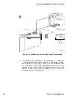
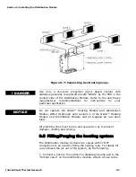
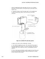
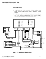
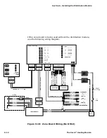
Page 76: ...Section 9 Installing the Distribution Module 9 14 The Oasis Heating Module...

Page 77: ...warranty Before mailing make photocopies of the completed Warranty Card for your records It will be a valuable reference if you need warranty repairs in the future General Warranty ITR warrants all wa...

Page 78: ...ance or repair of the Product or in connection with any services performed even if ITR has been advised of the possibility of such damages whether based upon warranty contract or negligence ITR s maxi...

Page 79: ...n brushes Product malfunctions due to improper installation of parts or Products including but not limited to malfunctions causing inadequacies in air fuel or coolant flow voltage problems due to impr...

Page 80: ...erial number of the Product on the outside of the shipping container and ship prepaid and insured 4 Provide written details of the problems date of installation proof of purchase and a return address...

Reviews: