background image

International Thermal Research 


8-1 

Operating the Hurricane

®


Chinook Heating System 

This  section  describes  the  features,  operation  and  maintenance 
of  your  new  Hurricane

®

  Chinook  Heating  System.  READ  THESE 

INSTRUCTIONS AND SAVE FOR REFERENCE.  

8.1  Features of Your Hurricane

®


Chinook Heating System 

The Hurricane

®

 Chinook Heating System uses a 50,000 BTU (true 

output)  diesel  burner  controlled  by  a  (12  VDC)  multi-functional 
electronic  controller  as  the  primary  source  of  heating  heat 
transfer fluid (anti-freeze and water).  Two 1500 Watt, 120 VAC 
immersion  elements  are  used  as  secondary  heat  sources  to 
provide  an  additional  10,000  BTU  of  heat.    The  Hurricane

®


Chinook Heating System heats the heat transfer fluid  to provide 
a  source  of  heat  for  all  hydronic  space  heating  needs.    Through 
the use of its integral distribution pumps, the Hurricane

®

 Chinook 

Heating  System  has  the  ability  to  circulate  the  heated  transfer 
fluid  to  all  space  heating  areas.    It  can  also  provide  a  supply  of 
domestic  hot  water  using  the  integral  heat  exchanger.  The 
Hurricane

®

  also  incorporates  engine  heat  and  optional  engine 

preheat functions. (see 

Figure 8-1:  Hurricane

®

 Chinook Heating 

System Overview)

.  

Other features of the Heating System include: 


Built  in  heat  transfer  fluid  (coolant)  distribution  pumps 
capable  of  supplying  coolant  to  multiple  heating  fans  in  a 
single loop, located in up to five different zones.  


An  internal  heat  exchanger  that  provides  potable  hot  water 
and use of engine waste heat and engine pre-heat (optional). 
For engine pre-heat,  an optional engine  pre-heat pump must 
be installed. 

Section 

Summary of Contents for Hurricane Chinook Heating System

Page 1: ...ricane Chinook Heating System has been designed to meet ABYC standards for installation in yachts This section covers critical information you need to know before beginning the installation including...

Page 2: ...l information for a proper installation A properly installed Hurricane Chinook Heating System is essential for several reasons To ensure that you and or your customers receive satisfactory results and...

Page 3: ...its integral fluid distribution pumps the Hurricane Chinook Heating System has the ability to circulate the heat transfer fluid to all space heating areas It can also provide a supply of potable hot w...

Page 4: ...rning a wide variety of diesel based fuels CSA UL certified for diesel 1 and 2 Exhaust has minimal smoke and smell Fan assisted sealed combustion chamber is designed to use outside combustion air Low...

Page 5: ...ors to keep in mind when planning and carrying out the installation are Mounting location restrictions for the Hurricane Chinook Heating System and exhaust outlet to reduce noise vibration heat loss e...

Page 6: ...anty You will need the following equipment and tools to install the heating system not supplied This list does not include optional equipment and accessories Standard tools normally available in a wel...

Page 7: ...he heating zones 1 6 Testing and Inspection After all components have been properly installed according to standard practices ABYC A 7 standards and the recommendations of this Installation and Operat...

Page 8: ...Section 1 Overview 1 8 The Hurricane Chinook Heating System...

Page 9: ...ne Chinook Heating System Hurricane Chinook Heating System weight when full 163 lbs Ventilation requirements Exhaust outlet location and maximum acceptable length including all 90 degree bends Refer t...

Page 10: ...e outside case of the Hurricane Chinook Heating System The serial number identifies the model type through the first series of letters and numbers 2 3 Your Mounting Location Your mounting location sho...

Page 11: ...ake connections The following are the minimum required clearances 12 top clearance 12 front clearance 0 clearance to all other Hurricane Chinook surfaces Allow 1 clearance on the left and right side f...

Page 12: ...be unduly affected by vibration and jarring from rough roads Ensure that the exhaust tubing can be properly and safely routed to the outside The maximum exhaust run for the system is 12 including 90 d...

Page 13: ...Mount the Zone Control Box containing the Zone Control Board vertically close to the Hurricane Chinook Allow sufficient room to access the internal fuses as well as to view the display LED s on the fr...

Page 14: ...g Panel Mounting Procedure The Touchscreen Remote Control Panel is mounted inside the yacht in an easy to access location An opening for the remote panel must be cut in a wall location or a mounting p...

Page 15: ...e drawn directly from the outside without coming in contact with air that can infiltrate the living areas See section 3 3 Never place any exhaust parts close to combustible material or through a combu...

Page 16: ...rface of the thru hull and the surface to which it is mounted and the thru hull is centered within the mounting hole A dual thru hull must be oriented such that the fresh air inlet hole on the side of...

Page 17: ...h an exhaust sealing compound to ensure the connection is tight and leak free All other exhaust connection must be made the same way Make sure the sealing compound does not restrict the exhaust flow T...

Page 18: ...ur mounting location accommodates the use of the fresh air inlet saddle pipe Make sure the temperature rise of any combustible material surrounding the exhaust parts does not exceed 50 C 90 F when the...

Page 19: ...ng to this fitting 6 Connect the fresh air inlet tubing to the saddle pipe on the thru hull Make sure the run of this tubing is as short as possible to provide good air flow Use a 32 gear clamp to att...

Page 20: ...Section 3 Installing the Exhaust System 3 6 The Hurricane Chinook Heating System Figure 3 1 Installing the Exhaust System...

Page 21: ...Heating System is not rated for use in an explosive environment Never share the fuel supply to the Hurricane Chinook Heating System with any other fuel burning device 4 2 Fuel System Installation The...

Page 22: ...leaks after installation and also periodically as part of normal maintenance A primary UL and or CSA approved fuel oil filter not provided must be installed inline on the fuel supply hose between the...

Page 23: ...tting on the main fuel tank 3 Connect the fuel return line to the fuel return fitting on the main fuel tank NOTICE The fuel return line from the heater may be connected to a common return line Make su...

Page 24: ...Section 4 Installing the Fuel System 4 4 The Oasis Chinook Heating System...

Page 25: ...ommended this switch be installed with this fan For best results the fans should be mounted as close to the floor as possible Some have a built in aquastat optional temperature sensing switch which tu...

Page 26: ...ll not run the fans unless the coolant inside the Hurricane Chinook tank is above 120F However during the initial startup the coolant in the lines will be lower than 120F until it has had a chance to...

Page 27: ...t heat for the installed heater unit Fan Guards to protect the fan blades from damage recommended for fans installed in storage areas or other accessible areas where something could contact the fan bl...

Page 28: ...ose the mounting locations of your fans Locate the fans to evenly heat the specific zone Provision must be made to protect potable water lines from freezing Install fan at floor level or very near flo...

Page 29: ...wire these up to the Zone Control Board in Section 6 Wiring The Electrical System 4 The Zone Control Board can control up to 5 zones The cabin fan 1 lead orange can supply up to a maximum of 10 Amps...

Page 30: ...Section 5 Installing Fan Heaters 5 6 The Hurricane Chinook Heating System Figure 5 2 Mounting a Low Profile Cabin Fan Figure 5 3 Installing a Relay for Additional Fan Amperage...

Page 31: ...eater Hurricane Chinook Remote Operating Panel Hurricane Chinook Zone Control Board Thermostats Cabin Fans To review the wiring for the Hurricane Chinook Heating System refer to the wiring diagram sho...

Page 32: ...d Green White Black White Black Black 110 VAC Battery _ Master Disconnect 25A Fuse 20A Fuse Battery _ Cabin Fans Thermostats Thermostat 1 White Thermostat 2 Yellow Thermostat 3 Pink Thermostat 4 Tan T...

Page 33: ...ower system is required for safe trouble free operation 6 3 Hurricane Chinook 120 VAC The Hurricane Chinook Heating System is equipped with two 1500 watt 120 VAC 60 Hz immersion elements The connectio...

Page 34: ...ntrol Board connects to the thermostats and cabin fans through a 14 pin plug with butt connect leads Cabin Fan leads refer to Fig 6 1 for system wiring information The positive red lead from each cabi...

Page 35: ...which is the only space heating pump in this system This will result in cold air blowing from the fans when only zones 3 4 or 5 are calling for heat See Section 8 Fig 8 6 for zone board jumper locatio...

Page 36: ...Section 6 Wiring the Electrical System 6 6 The Hurricane Chinook Heating System...

Page 37: ...a leak in the heat exchanger which could be caused if the fresh water in the system is allowed to freeze For an efficient Hurricane Chinook Heating System operation you must Minimize heat loss from th...

Page 38: ...EX Refer to Figure 7 3 for connecting PEX tubing to the 3 4 hose barb connections All fittings except the Heat Loop return fitting on the Hurricane Chinook require two wrenches when tightening One wre...

Page 39: ...Section 7 Plumbing the System International Thermal Research 7 3 Figure 7 1 Hurricane Chinook Overview Figure 7 2 Plumbing Hurricane Chinook for 5 Zones...

Page 40: ...e preceding fan The temperature difference will be larger if the fan has a higher BTU output The Hurricane Chinook should be filled and flushed prior to operation to remove any foreign debris Use heav...

Page 41: ...rs the bottom of the heating core and exits from the top This helps keep air from being trapped in the cabin fan core Ensure proper direction of flow See Figure 7 1 for the location of the fittings En...

Page 42: ...orresponding PEX fittings on top of the heater These connections are crimped using appropriate pex clamps The maximum potable water supply pressure to the heater is 150 PSI 10 bar The Hot water Outlet...

Page 43: ...hose is used 1 2 to 1 2 or 1 2 to 3 4 barb fittings can be used to make the connection to the engine See Sec 8 Fig 8 3 for location of the mixing valve If the optional engine pre heat function is req...

Page 44: ...un the engine pre heat pump without fluid or the pump will be damaged Figure 7 5 Engine Heat Pre heat System Plumbing 7 7 Procedure for Filling Purging the Hurricane Chinook Heating System 1 Do not op...

Page 45: ...the end of the suction hose from the pump into a reservoir of 50 50 heat transfer fluid propylene glycol based coolant and water Open the ball valve attached to the barbed fitting and turn ON the pump...

Page 46: ...OFF the Bypass Switch on the Zone Control Board This Bypass Switch should remain off during normal operation It is only used to fill and purge the system The shut off valve on the filler hose must be...

Page 47: ...ransfer fluid to provide a source of heat for all hydronic space heating needs Through the use of its integral distribution pumps the Hurricane Chinook Heating System has the ability to circulate the...

Page 48: ...steel burner and a 7 US gallon welded and insulated stainless steel coolant tank The coolant tank is designed to minimize heat loss and optimize heat recovery Domestic water flow switch for quick res...

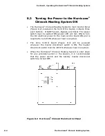
Page 49: ...tion and diagnostic information 8 2 Operating Instructions for the Hurricane Chinook Heating System The Hurricane Chinook Heating System must be installed and connections made in accordance with the r...

Page 50: ...pushed ON power LED will turn ON to turn the DC electrical power to the main control board ON and is required to be left ON whenever heat is required The Zone Control board Figure 8 4 will be powered...

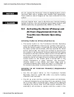
Page 51: ...burner will continue to operate until the coolant in the Hurricane Chinook reaches the set cycling temperature at which point the diesel burner will shut OFF If the system coolant should cool down bel...

Page 52: ...Heat Source Available Any thermostat connected to the Zone Control Board calling for heat will cause the cabin fan controlled by that thermostat and coolant circulation loop pump to activate The cabin...

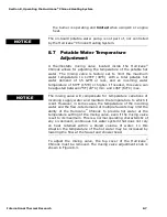
Page 53: ...etween 75F 24 C min and 145F 63 C max The mixing valve will compensate for temperature variations of incoming supply water and maintain the temperature to which it is set However in some cases the tem...

Page 54: ...8 Activating Engine Heat Pre heat Burner and or AC Heat On Pre heating the engine optional In order to use the engine pre heat feature and optional externally mounted pump must be installed see fig 7...

Page 55: ...and or the AC elements will remain off if enough heat is provided by the engine If the heat transferred from the engine is not sufficient to meet the space heating and potable hot water demand the bu...

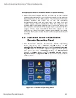
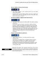
Page 56: ...the up arrow button is pushed a second time 3 0KW will be displayed indicating the current draw associated with two 120 VAC elements The electrical symbol will illuminate when AC power is available a...

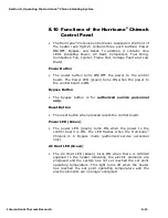
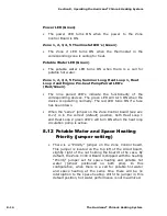
Page 57: ...n turns ON when the power to the control board is ON Bypass Button The bypass button is for authorized service personnel only Reset Button The reset button when pressed resets the control board Power...

Page 58: ...1 2 3 4 and 5 Thermostats and Potable Water It also contains nine matched pairings of red green LED s for Zone 1 2 3 4 and 5 Fans Summer Loop Heat Loop 1 Heat Loop 2 and Engine Pre heat Pump For the Z...

Page 59: ...the Summer Pump and circulate hot coolant from the heater through the section of the heat exchanger that transfers heat to the engine coolant At the same time the engine pre heat pump will turn ON an...

Page 60: ...e red LED turns ON if a fuse has been blown When the series jumper on the Zone Control board see sec 8 11 is in the correct default position both Heat Loop 1 and Heat Loop 2 green LED s will turn ON w...

Page 61: ...ies jumper Figure 8 6 Zone Control Board Jumper s location 8 13 Maintenance Customer Monthly Maintenance Check the following and correct as required Coolant hoses and fittings for leaks and integrity...

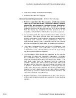
Page 62: ...heir remaining service life ending without any apparent visual signs or operating symptoms The major components such as the air compressor fuel pump fuel nozzle and combustion air fan should be examin...

Page 63: ...damage the internal parts including the heat exchanger For winterization it is recommended that the potable water system be flushed with winterizing antifreeze that is safe for use in the potable wat...

Page 64: ...circuit breakers tripped Burner Starts but Flame Faults Fuel nozzle plugged or dirty Fuel supply present and adequate Air intake or exhaust not blocked or obstructed Air in fuel line white smoke from...

Page 65: ...ecords It will be a valuable reference if you need warranty repairs in the future Limited Warranty The following warranties are in lieu of all other warranties and conditions ITR makes no other warran...

Page 66: ...Not Covered Under Warranty Warranty will be voided or not extended in the following circumstances Owner fails to notify ITR or the authorized ITR dealer from which the Product was originally purchased...

Page 67: ...blem have the following information ready at hand model number and serial number of the Product a detailed description of the problem your Installation Manual and Owner s Manual Depending on your loca...

Page 68: ...Telephone Email Service Service information given over the telephone by fax or by email is given only in good faith as an accommodation to the customer Such information should not be relied upon with...

Reviews: