Operation
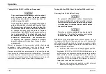
Towing Vehicle With Front Wheels Suspended
CAUTION
To prevent transmission damage, vehicles should
not be towed even short distances without
suspending rear wheels or removing the axle
shafts or propeller shaft.
In the event the chassis is equipped with tandem
axle and the vehicle is to be towed from the front,
the forward rear axle may be raised to clear the
road surface and secured to the frame by chains
or U-bolts, allowing only rear axle to contact
road surface. Axle shafts must be removed from
rear axle assembly. The wheel hub ends must
be covered to prevent loss of axle lubricant and
entrance of contaminants.
Use extreme care
in securing the chains or U-bolts to prevent
possible damage of brake lines, hoses or other
components.
When it is necessary to tow a vehicle with the front wheels
suspended,
extra
precautions
must
be
taken
to
avoid
transmission or differential damage. Proceed as follows.
Remove axle shafts from axle assembly to prevent the wheels
from driving the differential and the transmission. The wheel
hub ends must be covered to prevent loss of axle lubricant
and entrance of contaminants. If axle shafts are not removed,
removal of propeller shafts at rear axle will be required.
Towing Vehicles With Driver Controlled Differential Lock
Removing Axle Shafts Before Towing
CAUTION
To
prevent
differential
and/or
transmission
damage, vehicles that must be towed to a service
facility with the drive axle wheels on the ground,
it is necessary to remove the axle shafts before
the vehicle is towed.
CAUTION
Do not use a chisel or wedge to loosen axle shafts
and dowels. The chisel or wedge can damage
hub, axle shafts and oil seals if used.
NOTE: One of the axle shafts has two sets of splines. One set
to engage with differential side gear and one set to engage with
shift collar for the differential lock. It may be necessary to rotate
shaft slightly to align side gear spline teeth with clutch collar teeth
in order to remove axle shaft.
1.
Shift main differential to the locked (engaged) position.
Applicable RR DIFF or FR DIFF ENGAGE indicator must
be illuminated in instrument panel gauge cluster to validate
DIFF LOCK is FULLY engaged and axle shaft can be
removed.
Failure to fully engage axle DIFF LOCK will
allow DIFF LOCK shift collar to fall slightly and block, or
temporarily resist axle shaft reinsertion.
2.
Remove cap screws and washers or stud nuts and
washers from flanges of both axle shafts.
164
3878859R2
Summary of Contents for ProStar+ Eagle Series.
Page 4: ...Operator s Manual ProStar Series Printed in the United States of America 3878859R2 ...
Page 12: ...Table of Contents Section 10 Index Index 235 viii 3878859R2 ...
Page 26: ...Model Description Exterior Components 14 3878859R2 ...
Page 28: ...Model Description 16 3878859R2 ...
Page 59: ...Controls Features 3878859R2 47 ...
Page 70: ...Controls Features Declination Zone Map 58 3878859R2 ...
Page 93: ...Controls Features Center Dash Panel Wing Panel 3878859R2 81 ...
Page 128: ...Sleeper Features 116 3878859R2 ...
Page 182: ...Operation 170 3878859R2 ...
Page 241: ...Maintenance Intervals and Specifications Typical Interior Fuse Panel Layout 3878859R2 229 ...
Page 262: ...Index 250 3878859R2 ...

