ECM
BATTERY
200 A
F4
F-46
TO IDM RELAY
F-12
R
PDC
F40
2
IDM
STARTER
MOTOR
RELAY
KEY SWITCH
PDC#
F4
F12
F40
F46
R
Device
30A...IDM/ECM
20A...RUN/ACC
10A...IDM LOGIC
5A...ECM KEY PWR
IDM RELAY - POSITION 55
X1
X2
X3
X1
X2
X3
X3-8 IDM LOGIC POWER
X3-24 IDM MAIN POWER
X3-25 IDM MAIN POWER
X3-4 IDM MAIN POWER
X3-23 IDM MAIN POWER
X3-27 IDM MPR
X3-7 V
IGN
12
6
8
9
ENGINE IN-LINE
12-WAY
30
87
85
86
2
X1
X2
X3
X4
X1
X2
X3
X4
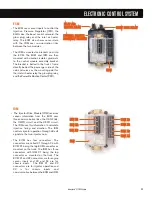
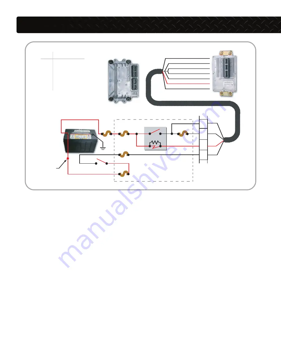
IDM Relay Circuit Operation
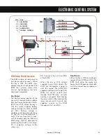
• The IDM controls its own power up
and power down process. When
the key is OFF, the IDM stays
powered up for a brief period. The
IDM then powers down after
internal housekeeping functions
have been completed.
IDM Power Up
• The key switch receives battery
voltage from the Power Distribution
Center (PDC) F-12 fuse. When the
key is ON, the switch supplies
battery voltage through F-46 fuse
and pin 9 of the engine 12-way
connector to pin X3-7 of the IDM.
• Battery voltage is available through
the PDC F-4 fuse to IDM relay pin
30 and 85 at all times. Pin 85
supplies voltage to the relay coil.
Pin 86 takes that voltage through
pin 8 of the engine 12-way
connector to pin X3-27 of the IDM.
When the key is ON, voltage
supplied to pin X3-7 signals the
IDM to provide a ground circuit to
pin X3-27. When this occurs,
current flowing through the IDM
relay coil builds a magnetic field
that causes the relay to latch. When
latched, the relay connects pin 30
to pin 87 and supplies current
through pin 12 of the engine in-line
12-way connector to pin X3-4, X3-
23, X3-24, and X3-25 of the IDM.
Four pins receive voltage to spread
the current draw over multiple pins.
IDM Logic
• The IDM also requires voltage for
the internal logic circuit. When the
IDM relay latches, pin 87 of the relay
supplies voltage to the IDM logic
circuit through the F-40 fuse in the
PDC. The F-40 fuse feeds through
pin 6 of the engine in-line 12-way
connector to the IDM pin X3-8.
ELECTRONIC CONTROL SYSTEM
28
International
®
VT 275 V6 Engine

