ELECTRONIC CONTROL SYSTEM
29
International
®
VT 275 V6 Engine
Temperature Sensor Operation
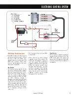
• There are four, two-wire temper-
ature sensors on the VT 275
engine. Each sensor contains a
resistor whose value varies depend-
ing on temperature. The ECM
supplies a separate reference
voltage to each temperature sensor.
Then, the sensor conditions its
voltage to produce the sensor signal.
Sensor Circuit
• A temperature variable resistor is a
thermistor. Each thermistor is
connected to a current-limiting
resistor of fixed value within the
ECM. The thermistor and the
resistor make a series circuit with a
reference voltage applied at one
end and a ground at the other. The
voltage in the circuit between the
two resistors changes as the
thermistor's resistance changes.
When the temperature is low, the
sensor's resistance is high and the
signal voltage is high. When the
temperature is high, the resistance
is low and the signal voltage is low.
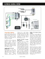
Engine Coolant Temperature
(ECT) Sensor
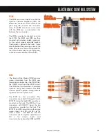
• The ECT sensor is mounted in the
front cover. The body of the sensor
is exposed to coolant as it returns
from the cylinder heads. The ECT
signal is input into the optional
engine warning protection system,
coolant compensation, glow plug
operation and the instrument
cluster temperature gauge.
Engine Oil Temperature
(EOT) Sensor
• The EOT sensor is mounted in the
oil filter adapter. The EOT signal
allows the ECM to compensate for
viscosity changes in the oil due to
temperature. The EOT signal is
input into calculations that
determine the fuel quantity and timing.
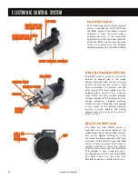
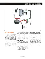
Manifold Air Temperature
(MAT) Sensor
• The MAT sensor is mounted
towards the front of the left bank leg
of the intake manifold. The MAT
sensor measures the temperature
of the air in the intake manifold. The
ECM uses this information in
calculations that control the EGR
valve operation.
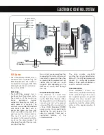
Intake Air Temperature
(IAT) Sensor
• The IAT sensor is contained within
the Mass Air Flow (MAF) sensor
housing. The MAF sensor is
mounted to the inlet duct leading to
the turbocharger. The ECM uses
the IAT information to control
injection timing and fuel rate when
starting cold.
ECM
VOLTAGE
RR
SENSOR
IDM
ECM
X1
X2
X3
X4
E DC B A
IAT
X1-7 IAT
X1-6 GRD
X1-8 ECT
X2-1 EOT
X2-14 MAT
MAF / IAT
EGR
DRIVE
MODULE
IAH RELAY
GLOW PLUG
RELAY
BCS
IPR
EGR
VALVE
ECT
EOT
MAT
RIGHT BANK INJECTORS
LEFT BANK INJECTORS
REFERENCE
VOLTAGE
MICRO-
PROCESSOR
R
R
1
1
2
2
X1
X2
X3
X1
X2
X3


