ELECTRONIC CONTROL SYSTEM
39
International
®
VT 275 V6 Engine
A/C Clutch Control
• The VT 275 ECM controls the A/C
clutch. The ECM receives an A/C
demand signal from the chassis,
and engages the A/C clutch if
engine conditions are correct. If
conditions are not right, clutch
action may be delayed. When the
ECM receives the A/C demand
signal, it considers engine run time
(to avoid stalling at start up) and
engine coolant temperature (to
avoid compressor operation when
liquid refrigerant may be present in
the compressor). In addition, the
ECM looks at transmission shift
action (to avoid clutch action during
a transmission shift), engine RPM
(to avoid clutch overspeed), and
APS percent (to avoid engagement
during full throttle acceleration).
A/C Demand
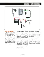
• The A/C demand signal originates
at the ECM as a reference voltage
on X3-10. The ECM supplies 5
volts to pin 10 and considers clutch
engagement when the voltage is
pulled low (shorted to ground) by
the A/C on/off switch in the dash-
located A/C Control Head.
The low-pressure switch (LPSW),
high-pressure switch (HPSW), and
the thermostat switch (T-STAT SW)
are in series in the A/C demand
circuit. If the compressor head
pressure rises above 350 psi, the
high-pressure switch opens and the
demand signal will be 5V. If
pressure on the low side of the
compressor goes below 7 psi, the
low-pressure switch will open and
the demand signal will be 5V.
The last switch is the thermostat
control in the A/C Control Head. If
the thermostat is positioned so that
in-cab temperature demands are
satisfied, the thermostat will open
and the demand signal will be 5V.
A/C Control
• If the A/C demand signal is pulled
low and the ECM determines that
the clutch can be engaged, the
ECM pulls the AC Control circuit
low at pin X3-22. When pin 22 is
low, a ground is provided for the
A/C Clutch Relay. The relay latches
and battery voltage is provided to
the A/C clutch through pin 5 of the
engine 12-way connector.
Switches
• The thermostatic switch (T-STAT
SW) monitors evaporator core
temperature to prevent freezing and
to regulate cab temperatures.
• The low pressure switch (LPSW)
prevents compressor damage in the
event of a refrigerant leak.
• The high pressure cutoff Switch
(HPSW) interrupts compressor
operation in the event of high
system pressures.
ECM
F34
F12
PDC
FUNCTION SELECTOR
SWITCH
HPSW
LPSW
T-STAT SW
ECT
TO
TRANS
CONTROLLER
X3-10 AC DEMAND
CAN1+
CAN 1(+)
CAN1-
CAN 1(-)
X3-22 AC CONTROL
TO IGN
SW
IGNITION
SWITCH
200A
MEGA
FUSE
TO BATTERY
POSITIVE
h
X1
X2
X3
X4
X1
X2
X3
X4
7
5
1
CA
2
CMP
APS
BATTERY
GRD
A/C
CLUTCH
A/C CLUTCH
DIODE
A/C CLUTCH
RELAY
3
5
1
2


