background image

VT 275 OVERVIEW

Slide Title Goes Here

6

International

®

VT 275 V6 Engine

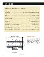
VT 275 ENGINE SPECIFICATIONS

Engine Type  . . . . . . . . . . . . . . . . . . . . . . . . . . . . . . . . . . . . . . . . 4-stroke, direct injection diesel

Configuration  . . . . . . . . . . . . . . . . . . . . . . . . . . . . V6, pushrod operated four valves / cylinder 

Displacement  . . . . . . . . . . . . . . . . . . . . . . . . . . . . . . . . . . . . . . . . . . . . . . 275 cu. in. (4.5 liters)

Bore  . . . . . . . . . . . . . . . . . . . . . . . . . . . . . . . . . . . . . . . . . . . . . . . . . . . . . . . . . 3.74 in.  (95 mm)

Stroke  . . . . . . . . . . . . . . . . . . . . . . . . . . . . . . . . . . . . . . . . . . . . . . . . . . . . . 4.134 in.  (105 mm)

Compression Ratio  . . . . . . . . . . . . . . . . . . . . . . . . . . . . . . . . . . . . . . . . . . . . . . . . . . . . . . 18.0:1

Aspiration  . . . . . . . . . . . . . . . . . . . . . . . . . . . . . . . . . Twin turbocharged and charge air cooled

Rated Power . . . . . . . . . . . . . . . . . . . . . . . . . . . . . . . . . . . . . . . . . . . . . . . . 200 hp @ 2700 rpm

Peak Torque  . . . . . . . . . . . . . . . . . . . . . . . . . . . . . . . . . . . . . . . . . . . . . . . 440 lb-ft @ 1800 rpm

Engine Rotation, Facing the Flywheel  . . . . . . . . . . . . . . . . . . . . . . . . . . . . . Counterclockwise

Injection System  . . . . . . . . . . . . . . . . . . . . . . . . . Electro-hydraulic generation 2 fuel injection

Cooling System Capacity (Engine Only)  . . . . . . . . . . . . . . . . . . . . . . . . . . . . . . . . . . 11 quarts

Lube System Capacity (Engine Only) . . . . . . 13 quarts with oil filter (14 quarts at overhaul)

0

50

100

150

200

250

300

350

400

450

500

600

800

1000

1200

1400

1600

1800

2000

2200

2400

2600

2800

3000

3200

3400

3600

0

25

50

75

100

125

150

175

200

225

250

Torque (ft-lb)

Power (HP)

Engine Speed (RPM)

Load (ft-lb)

Po

w

er

 (H

P)

Power & Torque Curve

Horsepower and Torque

• The VT 275 engine is offered with only one

horsepower and torque rating for the 2005
model year. The engine creates 200
horsepower at 2700 rpm and 440 lb-ft of
torque at 1800 rpm. The engine has a
high idle speed of 2775 rpm with
automatic transmission. The engine idle
speed is set at 700 rpm and is not adjustable.

Summary of Contents for VT 275 V6

Page 1: ...VT 275 V6 ENGINE model year 2005...

Page 2: ...rk in bare feet sandals or sneakers Wear appropriate hearing protection Wear correct clothing Do not wear rings watches or other jewelry Restrain long hair F Fi ir re e p pr re ev ve en nt ti io on n...

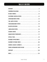
Page 3: ...M 22 AIR MANAGEMENT SYSTEM 40 FUEL SUPPLY SYSTEM 48 FUEL MANAGEMENT SYSTEM 52 INJECTOR OPERATION 56 LUBRICATION SYSTEM 60 COOLING SYSTEM 68 UNIQUE REPAIR PROCEDURES 72 SPECIAL TOOLS 86 DIAGNOSTIC PROC...

Page 4: ...4...

Page 5: ...EL ENGINE 90 V6 Offset Crankpins Rear Gear Train Primary Balancer Regulated Two Stage Turbocharging System Four Valves per Cylinder Cooled Exhaust Gas Recirculation Electro Hydraulic Generation 2 Fuel...

Page 6: ...fuel injection Cooling System Capacity Engine Only 11 quarts Lube System Capacity Engine Only 13 quarts with oil filter 14 quarts at overhaul 0 50 100 150 200 250 300 350 400 450 500 600 800 1000 1200...

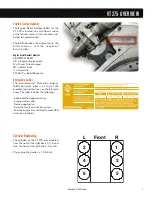
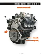
Page 7: ...uence Emissions Label The Environmental Protection Agency EPA emissions label is on top of the breather toward the front on the left valve cover The label includes the following Advertised horsepower...

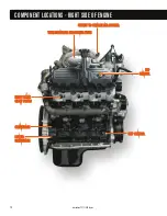
Page 8: ...CK K V VA AL LV VE E C CH HE EC CK K V VA AL LV VE E I IN NT TA AK KE E M MA AN NI IF FO OL LD D I IN NT TA AK KE E M MA AN NI IF FO OL LD D M MA AT T S SE EN NS SO OR R M MA AT T S SE EN NS SO OR R...

Page 9: ...L LL LE EY Y S SM MO OO OT TH H I ID DL LE ER R P PU UL LL LE EY Y C CO OO OL LA AN NT T O OU UT TL LE ET T C CO OO OL LA AN NT T O OU UT TL LE ET T H HE EA AT TE ER R H HE EA AT TE ER R R RE ET TU UR...

Page 10: ...RI IM MA AR RY Y F FI IL LT TE ER R A AN ND D P PR RI IM MA AR RY Y F FI IL LT TE ER R F FU UE EL L R RE ET TU UR RN N T TO O T TA AN NK K F FU UE EL L R RE ET TU UR RN N T TO O T TA AN NK K L LE EF F...

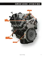
Page 11: ...NG G E EY YE ES S L LE EF FT T B BA AN NK K L LE EF FT T B BA AN NK K E EX XH HA AU US ST T M MA AN NI IF FO OL LD D E EX XH HA AU US ST T M MA AN NI IF FO OL LD D R RE EA AR R C CO OV VE ER R R RE EA...

Page 12: ...HO OU US SI IN NG G O OI IL L F FI IL LT TE ER R H HO OU US SI IN NG G E EX XH HA AU US ST T T TU UB BE E A AS SS SE EM MB BL LY Y E EX XH HA AU US ST T T TU UB BE E A AS SS SE EM MB BL LY Y H HI IG...

Page 13: ...R H HO OU US SI IN NG G H HI IG GH H P PR RE ES SS SU UR RE E C CO OM MP PR RE ES SS SO OR R H HO OU US SI IN NG G U UP PP PE ER R O OI IL L P PA AN N U UP PP PE ER R O OI IL L P PA AN N L LO OW WE E...

Page 14: ...AI IR R C CO OO OL LE ER R O OU UT TL LE ET T T TO O C CH HA AR RG GE E A AI IR R C CO OO OL LE ER R I IC CP P I IC CP P S SE EN NS SO OR R S SE EN NS SO OR R C CK KP P S SE EN NS SO OR R C CK KP P S...

Page 15: ...RI IV VE E A AN ND D F FA AN N D DR RI IV VE E P PN NE EU UM MA AT TI IC C A AC CT TU UA AT TO OR R P PN NE EU UM MA AT TI IC C A AC CT TU UA AT TO OR R B BO OO OS ST T C CO ON NT TR RO OL L S SO OL...

Page 16: ...S I IN NJ JE EC CT TO OR R C CO ON NN NE EC CT TO OR RS S E EO OP P S SW WI IT TC CH H E EO OP P S SW WI IT TC CH H E EO OT T S SE EN NS SO OR R E EO OT T S SE EN NS SO OR R L LO OW W P PR RE ES SS SU...

Page 17: ...S SO OR R N NO OT T S SH HO OW WN N A AL LT TE ER RN NA AT TO OR R F FU US SI IB BL LE E L LI IN NK KS S A AL LT TE ER RN NA AT TO OR R F FU US SI IB BL LE E L LI IN NK KS S A AL LT TE ER RN NA AT TO...

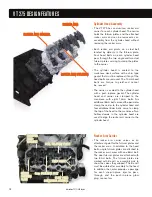
Page 18: ...nder head are used to align the rocker arm carrier to the cylinder head Rocker Arm Carrier The rocker arm carrier serves as an attachment point for the fulcrum plates and the rocker arms In addition t...

Page 19: ...6mm bolts Oil pulled through the oil pickup tube passes through a passage cast in the upper oil pan to the lower crankcase The lower crankcase has a machined passage that takes oil to a front cover p...

Page 20: ...ote The crankshaft gear that drives the camshaft is located behind the flange gear Gear Timing The camshaft and balance shaft must be timed to the crankshaft for proper engine operation During reassem...

Page 21: ...ce is created when two or more forces act on the crankshaft at different points along its length Couple imbalance if not offset results in pitch and yaw forces on the engine that are felt by the vehic...

Page 22: ...m The electronic control system features an Engine Control Module ECM and an Injector Drive Module IDM The Exhaust Gas Recirculation EGR valve is positioned by an ECM controlled electric stepper motor...

Page 23: ...has four connectors The connectors are called X1 through X4 with ECM X1 being the top ECM connector as mounted on the truck The IDM has three connectors with IDM X1 being the top connector as mounted...

Page 24: ...GR valve The drive module uses the sensor signals to determine the percent of valve opening Inlet Air Heater Element The Inlet Air Heater element is located in the lower side of the intake manifold an...

Page 25: ...open terminal connects to the element through the harness One end of the relay coil is grounded through the engine 12 way connector The relay closes when the coil receives voltage from the ECM Inject...

Page 26: ...S ST T I IN NL LE ET T E EX XH HA AU US ST T I IN NL LE ET T E EX XH HA AU US ST T O OU UT TL LE ET T E EX XH HA AU US ST T O OU UT TL LE ET T E EX XH HA AU US ST T E EX XH HA AU US ST T O OU UT TL LE...

Page 27: ...n X3 5 of the ECM When the key is ON voltage supplied to pin X3 3 signals the ECM that the operator is going to start the engine The ECM then supplies a ground circuit to pin X3 5 When this occurs cur...

Page 28: ...pin X3 7 of the IDM Battery voltage is available through the PDC F 4 fuse to IDM relay pin 30 and 85 at all times Pin 85 supplies voltage to the relay coil Pin 86 takes that voltage through pin 8 of...

Page 29: ...er heads The ECT signal is input into the optional engine warning protection system coolant compensation glow plug operation and the instrument cluster temperature gauge Engine Oil Temperature EOT Sen...

Page 30: ...system Manifold Absolute Pressure MAP sensor The MAP sensor is a variable capacitance style sensor In a variable capacitance sensor the pressure being measured deflects a ceramic disk towards a metal...

Page 31: ...ut as the TACH signal for body builder use Crankshaft Position CKP Sensor The CKP sensor is mounted on the right front of the lower crankcase The CKP sensor reacts to a sixty minus two tooth trigger w...

Page 32: ...on terminal from the starter power feed terminal The normally open terminal connects to the individual glow plugs through the glow plug harness One end of the relay coil is always grounded through pin...

Page 33: ...cted the inlet air heater is disabled Relay Operation The IAH relay receives battery power from the starter power feed terminal The normally open terminal connects to the element through the harness O...

Page 34: ...element placed in the air stream The amount of electrical power needed to maintain the element at the proper temperature depends directly on the mass of air moving over the element Sensor Operation Th...

Page 35: ...or The ECM monitors the relay s operation through ECM pin X4 15 Battery voltage should be present at X4 15 when the relay is commanded on If the ECM does not detect the voltage a DTC will be logged Fu...

Page 36: ...ECM will ignore the APS signal and operate at low idle If a disagreement in the state of IVS and APS is detected by the ECM and the ECM determines that the IVS is at fault the ECM will allow a maximum...

Page 37: ...the coil sets is controlled by the EGR Drive Module When the integrated circuit in the module connects one coil set to ground and one of the other two coil sets to a Pulse Width Modulated PWM power s...

Page 38: ...odule monitors the valve action and communicates any faults back to the ECM over the CAN 2 link Cam Position Output CMPO The CMPO signal is a 0 12V digital signal used to communicate the camshaft posi...

Page 39: ...high pressure switch opens and the demand signal will be 5V If pressure on the low side of the compressor goes below 7 psi the low pressure switch will open and the demand signal will be 5V The last...

Page 40: ...anagement System Regulated two stage turbocharger Cooled exhaust gas recirculation Intake air heater 40 International VT 275 V6 Engine System Features The Air Management System consists of the air fil...

Page 41: ...st flow through a passage that allows a portion of the exhaust to bypass the high pressure turbine and go directly to the low pressure turbine Part of the exhaust gas that leaves the left bank exhaust...

Page 42: ...t high idle no load with a magnehelic gauge Intake Manifold The intake manifold directs air from the charge air cooler to the intake ports in the cylinder heads The manifold also provides an internal...

Page 43: ...ure turbocharger results in improved response and higher low speed boost capability providing improved low speed engine torque The compounding capability of the two turbos in the mid range results in...

Page 44: ...ening and through a port cast into the high pressure turbine housing The exhaust flow exits at the inlet to the low pressure turbine 44 International VT 275 V6 Engine H HI IG GH H P PR RE ES SS SU UR...

Page 45: ...or opens the diverter valve Actuator Line Routing The ECM controls the venting of the actuator through the Boost Control Solenoid BCS Proper operation of the pneumatic actuator is dependent on the rou...

Page 46: ...ounting surfaces In addition the oil drain tube assembly is made of three pieces and allows for changes in the mounting points Note Removal of the turbocharger will change the relationship of the two...

Page 47: ...pe assembly are directed to the EGR cooler Gases flowing through exhaust passages in the cooler lose heat energy to engine coolant flowing through the coolant passages in the cooler The cooled exhaust...

Page 48: ...from the fuel in the HFCM is detected by the Water in Fuel WIF sensor The sensor is an input to the ECM which controls the WIF dash lamp through the CAN 1 link The HFCM has both an electric fuel heat...

Page 49: ...the cylinder head with a banjo bolt Each bolt contains an orifice and a check valve Once in the head passages fuel is distributed to the injectors Fuel is exposed to the pressure regulator in the sec...

Page 50: ...trolled by the key switch start run circuit and is self regulating The heater comes on when fuel temperature is below 50 F 10 C and goes off at 80 F 27 C Return fuel from the engine is recirculated to...

Page 51: ...g through the filter enters steel lines that lead to the right and left bank cylinder heads Each line is attached to the cylinder head with a banjo bolt that contains a one way check valve and a small...

Page 52: ...e high pressure pump The high pressure pump is mounted at the rear of the crankcase Vee and is gear driven off the rear gear train The Injection Control Pressure ICP sensor is mounted on the right ban...

Page 53: ...e rail can then enter the top of the injector As each injector spool valve opens oil pushes the intensifier piston down pressurizing the fuel below the plunger Fuel pressure acts on the bevel of the n...

Page 54: ...f the pump cover is sealed at the cover opening with an O ring Injection Pressure Regulator The Injection Pressure Regulator IPR mounts on the high pressure pump The pump moves more oil than the syste...

Page 55: ...lign with the injector openings The rail does not need to be drained before removal Port Plugs and Tubes There is one O ring sealed case to head tube assembly for each bank of cylinders The case to he...

Page 56: ...essure pump to provide the mechanical force needed to inject fuel into the cylinders Each injector has two coils The IDM selectively signals the coils with 48 volts to control the position of the spoo...

Page 57: ...dle closed At that point the needle lifts and fuel under high pressure passes through the nozzle holes Intensifier Piston Since the intensifier piston is approximately seven times greater in surface a...

Page 58: ...r Oil Pressure Fuel Pressure High Pressure Oil Atmosphereic Pressure Fuel Supply Pressure Above 3100 PSI Injection The injector drive module energizes the open coil and the spool valve moves to the op...

Page 59: ...KE ET T Oil Pressure Fuel Pressure High Pressure Oil Atmosphereic Pressure Fuel Supply Pressure Above 3100 PSI End of injection When the injector drive module determines that the correct amount of fu...

Page 60: ...egulator end plug The oil cooler is located under the oil cooler cover in the engine s Vee The cooler occupies a portion of the space in the high pressure reservoir The oil filter is a canister style...

Page 61: ...reservoir and the crankcase passages Cooled and filtered oil enters two oil passages at the top of the crankcase The right passage leads to the right bank oil galley where oil is directed to the cran...

Page 62: ...flows from the lower crankcase to the oil pump through a passage in the back of the front cover When the crankshaft turns the oil pump oil pulled from the oil pan is pushed from a passage in the front...

Page 63: ...The regulator which can be removed with the engine in the chassis is located in the front cover just below the gerotor oil pump cover The face of the regulator piston is exposed to the pressurized oi...

Page 64: ...se to the to the cooler cover Coolant passes through the oil cooler and exits at the EGR cooler supply port The oil filter adapter mounts the oil pressure switch and the oil temperature sensor and fee...

Page 65: ...The top of the oil filter element has a hole that matches the location of the valve Unfiltered oil surrounds the filter including the top of the filter and the bypass valve The valve opens if there is...

Page 66: ...sure during cold start up Reservoir and Screen The oil reservoir for the high pressure oil pump is located under the oil cooler cover in the crankcase Vee The reservoir holds approximately one quart a...

Page 67: ...ht bank tappets piston cooling jets and the main bearings and cam bearings 4 Coolant Feeds coolant from the water pump to the oil cooler and the EGR cooler 5 Filter Drain Allows drain oil from the fil...

Page 68: ...e front cover The water pump pushes coolant through two ports on the front cover to matching ports on the crankcase Coolant flows through the crankcase and cylinder passages then returns to the front...

Page 69: ...the crankcase The cooler cover directs the coolant through the oil cooler and then into the EGR cooler via the intake manifold The oil cooler bundle is sealed at the cover with two O rings at both the...

Page 70: ...nlet to oil cooler cover seal consists of both a rubber seal and an O ring Glow Plug and Injector Sleeves The VT 275 uses stainless steel injector sleeves to seal coolant from the injectors The inject...

Page 71: ...s 150 000 miles or 6 000 hours See the Engine Operation and Maintenance Manual for the hours and gallons of fuel component for the correct oil change interval Belt tensioner Smooth idler pulley Smooth...

Page 72: ...with a wear sleeve The wear sleeve must not be removed from the seal prior to installation International VT 275 V6 Engine UNIQUE REPAIR PROCEDURES H HE EE EL L B BA AR R H HE EE EL L B BA AR R R RE E...

Page 73: ...nter to evenly pull down the flexplate UNIQUE REPAIR PROCEDURES Seal Installer Base Place a 360 bead of Loctite Hydraulic Sealant on the outer circumference of the crankshaft flange Bolt the base of t...

Page 74: ...r Loosen and remove the four exhaust flange bolts Removing Mounting Bolts Remove three turbocharger mounting bolts that mount the low pressure turbocharger turbine housing to the high pressure pump co...

Page 75: ...lowed to align correctly to the exhaust pipe assembly First torque the three turbocharger to pump cover mounting bolts Torque Turbine Mating Clamp Second torque the exhaust pipe assembly to the manifo...

Page 76: ...nstall a new O ring on the other end of the crossover tube Assemble the crossover tube to the turbocharger so the clamp bolt will be vertical with the turbocharger on the engine A small amount of soap...

Page 77: ...removed Note The port plug and case to head tube s O rings are not replaceable The port plug and case to head tube must be replaced if the O rings are damaged Injector Connectors The injector connecto...

Page 78: ...Head Tube Installation If the tube does not pull out with the port plug it will need to be removed after the rail is removed using the Case to head Tube Removal Tool ZTSE4694 Before installation lubr...

Page 79: ...rt the injector s hold down clamp into the base of tool Install the assembly as if installing an injector Snug the hold down bolt but do not torque Note Use clean shop towels to plug any oil drain hol...

Page 80: ...Head Removal Continued The rocker arms push rods and valve bridges must be installed in their original position during reassembly The valve bridges can be marked with a permanent marker during disasse...

Page 81: ...lts are tightened to specifications Intake Manifold Gaskets The intake manifold gaskets must be oriented correctly upon reassembly After the intake manifold is assembled to the engine the gasket would...

Page 82: ...head bolts lightly lubricated Torque bolts 1 through 8 in sequence to 65 lb ft 88 Nm Torque bolts 1 3 5 and 7 to 85 lb ft 116 Nm Torque bolts 2 4 6 and 8 to 85 lb ft 116 Nm Tighten all bolts 1 throug...

Page 83: ...Crankshaft Flange Bolts The crankshaft flange is pressed on and bolted to the crankshaft during manufacturing To prevent engine damage do not remove the crankshaft flange bolts under any circumstance...

Page 84: ...e crankcase before removing the cover Caution To prevent engine damage cut the sealant where the crankcase and lower crankcase meet when removing the front cover Failure to adequately cut the sealant...

Page 85: ...gn the timing pin through the hole in each gear and insert the timing pin tool through the gears until it engages the crankcase hole Align the dot on the balance shaft with the dot on the face of the...

Page 86: ...Socket Part No 180971C91 Oil Fill Extension ZTSE4690 ICP Adapter Plug Kit ZTSE4670 Glow Plug Connector Remover Installer ZTSE4698 Fuel Inlet Restriction Adapter ZTSE4515A Rear Seal Wear Sleeve install...

Page 87: ...E4685 EGR Valve Puller Arm offset ZTSE4559 Intake Port Magnetic Covers ZTSE4531 Glow Plug Sleeve Remover ZTSE4669 EGR Valve Puller ZTSE4545 EGR Cooler Test Plates ZTSE4694 Case to head Tube Removal To...

Page 88: ...ess ZTSE4664 EGR Valve Breakout Harness ZTSE7559 Vacuum Pump and Gauge ZTSE4525 Oil Cooler Test Plate Pressure Adapter ZTSE4695 MAF IAT Sensor Breakout Harness ZTSE4696 Fuel Pressure Test Adapter ZTSE...

Page 89: ...fold Pressure Test Cap ZTSE4409 Gauge Bar Tool ZTSE4680 Front Seal Installer Wear Sleeve Installer ZTSE4557 Oil Cooler Reservoir High Pressure Pump Magnetic Covers ZTSE4526 Fuel Oil Pressure Test Coup...

Page 90: ...c o t n r e c n o c g n i t r a t s a s s e l n u s n i a m e r s n o i t a c i f i c e p s e n i g n e r o f 5 0 3 S E G E n i A x i d n e p p A e e S r o f 1 0 1 3 E G C m r o F r o 5 0 3 S E G E n...

Page 91: ...5 4 3 r e v O V 2 8 0 t f e L t h g i R i s p 0 0 5 a p M 5 4 3 r e v O V 2 8 0 d e d o r r o C s r o t c e n n o c R P I s n i p k c a b d e h s u p r o t n e b 2 3 1 n o i t c n u f R P I 3 3 1 e v...

Page 92: ...n o i t a c i f i c e p s n i s i e r u s s e r p e g r a h c s i d p m u p f I e v l a v r o t a l u g e r 3 5 t s e t o d d l i u b o t w o l s r o w o l s i e r u s s e r p e g r a h c s i d f I l...

Page 93: ...r u s s e r p l a u t c A c e p S t n e m u r t s n I e g u a g i s p 0 6 1 0 r o t i n o m o t T S E e s U e r u s s e r p t s o o b d e e p s e n i g n e d n a e u n i t n o c n o i t a c i f i c e...

Page 94: ...tion Check for Fuel Aeration The engine will not operate correctly with aerated fuel Aeration can be checked visually using a clear hose and valve Remove the fuel pressure test port plug Connect the F...

Page 95: ...r a plugged primary filter and or high pump inlet restriction Measure Fuel Inlet Restriction High inlet restriction can starve the suction side of the fuel pump and cause low fuel pressure With the ke...

Page 96: ...Compression test to further evaluate high readings Oil reservoir High pressure pump IPR valve Fuel injectors Oil rail Oil rail Check valve with orifice Check valve with orifice Oil drain to sump ICP s...

Page 97: ...594 with an air fitting in place of the sensor Remove the oil fill cap and attach shop air pressure to the air fitting Listen at the opening of the oil fill cap for air leaking into the crankcase from...

Page 98: ...but the location cannot be detected isolate each bank one at a time and test To test the left bank remove the left bank rear port plug and install the ICP Leak Test Plug ZTSE4690 in place of the port...

Page 99: ...O OR R A AD DA AP PT TE ER R I IC CP P S SE EN NS SO OR R R RI IG GH HT T B BA AN NK K R RA AI IL L KOEO Standard Test ICP System Function Test IPR Function Test Under the Valve Cover Leak Test Cylind...

Page 100: ...of range high Barometric Absolute Pressure signal out of range low Air Inlet Temperature signal out of range low Air Inlet Temperature Signal out of range high Manifold Air Temperature Signal out of r...

Page 101: ...rcuit fault High side to low side open cylinder number indicated High side shorted to low side cylinder number indicated High side short to ground or VBAT cylinder number indicated IDM VIGN voltage lo...

Page 102: ...L R Y G W R B K B G L G L B D W R R G L O R B R G L R O Y G B D O P R Y G L W R B K P K B P Y G L O B D O P K B G L R W B L R W 9 8 7 6 K B n i a r D d l e i h S r o s n e S n o i t i s o P R G G L R...

Page 103: ...d n a s t n e m e v o r p m i t c u d o r p e c u d o r t n i o t e d a m r o f l a u n a m e c i v r e s k c u r t t c e r r o c e e S s t n e m e c n a v d a g n i r i w s i s s a h c s l a n i m r...

Page 104: ...POWER DISTRIBUTION CENTER 104 International VT 275 V6 Engine Consult service literature for latest information before attempting any repairs...

Page 105: ...MODULE 30A CONJOINER 1 30A CONJOINER 2 40A TRAILER BATT 20A CIGAR LIGHTER 20A HAZARD 15A KEYLESS 10A RADIO 10A DOME BLANK 60A ABS PUMP 31 32 33 34 35 36 37 38 39 40 41 42 43 44 45 46 47 48 49 50 51 5...

Page 106: ...1 A data link between the vehicle modules and ECM CAN 2 The private link between the ECM and IDM Catalytic Converter An antipollution device in the exhaust system that contains a catalyst for chemica...

Page 107: ...ature Manifold Absolute Pressure MAP Boost pressure in the manifold that is a result of the turbocharger Manifold Absolute Pressure MAP Sensor A variable capacitance sensor that measures boost pressur...

Page 108: ...67 71 106 Coolant Heater 13 Counter Weight 21 Crankcase Breather 40 Crossover Tube 14 41 46 75 76 Cruise Control 36 Crankcase Pressure 96 Crankpins 5 21 Crankshaft Position Output CKPO 23 31 38 101 C...

Page 109: ...ference Voltage VREF 36 107 Rear Cover 11 72 84 85 Rear Gear Train 5 20 Rocker Arm 18 79 80 S Secondary Fuel Filter 48 51 Sensors Barometric Absolute Pressure BAP Sensor 36 106 Camshaft Position CMP S...

Page 110: ...110 International VT 275 V6 Engine NOTES...

Page 111: ...111 International VT 275 V6 Engine NOTES...

Page 112: ...2005 INTERNATIONAL TRUCK AND ENGINE CORPORATION TMT 120502 PRINTED IN THE U S A...

Reviews: