


9
R05
S
AFETY
I
SSUES
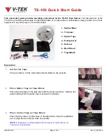
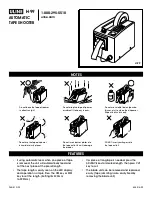
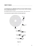
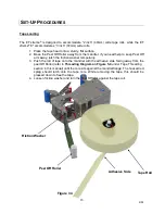
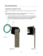
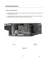
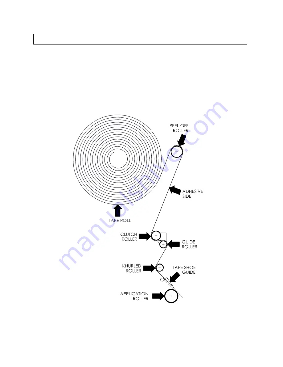
The illustrated label shown in
Figure 5-4
is attached to the operator side plate of each tape
head. The label provides operators and service personnel the proper method of threading a
new roll of tape through the tape head.
More detailed information is provided in the “Set Up Procedures” portion of this manual.
Turn air and electrical supplies off before servicing the tape heads.
Figure 5-4
Summary of Contents for ET xtreme Series
Page 1: ...1 R05 ET xtreme STANDARD TAPE HEAD Serial Numbers UH230T UH430T ...
Page 2: ...2 R05 ...
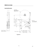
Page 10: ...10 R05 SPECIFICATIONS UUUTape Head Dimensions Figure 6 1 ...
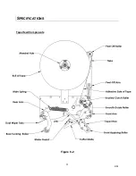
Page 11: ...11 R05 SPECIFICATIONS UUU Tape Head Components Figure 6 2 ...
Page 43: ...43 R05 THIS PAGE INTENTIONALLY LEFT BLANK ...
Page 44: ...4 6 10 8 1 9 3 5 7 2 11 12 13 44 ...
Page 46: ...1 15 2 3 6 10 12 14 7 11 8 9 5 4 16 14 13 13 4 18 17 46 ...
Page 48: ...6 11 8 14 2 12 9 7 10 5 3 3 13 48 ...
Page 50: ...6 7 15 11 10 14 4 2 9 3 5 13 12 8 1 16 50 ...
Page 52: ... 8 8 ...
Page 53: ... 7 0 3 57 6 5 37 21 8 47 8 47 83 8 52 5 83 2035 66 21 635 1 83 8 52 5 ...
Page 54: ...2 4 1 5 3 54 ...
Page 56: ... 8 8 ...
Page 58: ... 86 86 ...
Page 60: ...2 4 1 3 5 6 5 60 ...
Page 62: ...2 3 6 5 1 8 4 12 9 7 9 10 11 62 ...
Page 64: ...5 15 7 6 12 2 14 4 3 13 10 8 9 1 11 16 64 ...
Page 66: ...3 1 2 2 1 3 Standard Tape Head Mirror Tape Head 66 ...
Page 68: ...5 2 10 4 11 3 8 6 7 1 9 12 68 ...
Page 70: ...1 3 2 70 ...
Page 72: ... 8 8 ...
Page 74: ...6 1 2 5 3 4 74 ...
Page 76: ...19 4 9 16 6 7 5 8 1 11 3 10 14 12 15 13 18 17 2 20 76 ...
Page 78: ...1 2 No Tape options are available 78 ...