UH179TW
/
UH679TW
UDH179-02
24
T
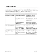
ROUBLESHOOTING
,
C
ONTINUED
T
ROUBLE
P
OSSIBLE
C
AUSES
S
OLUTIONS
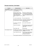
“Tape Tabbing
” or folding
on itself on the trailing tape
leg
Generally, too much tension
on the application of the tape.
Follow steps below
Applying urethane rollers,
delrin guide rollers, knurled
metal rollers should spin
freely. Check for any
adhesive migration or build
up
Too much mandrel tension
Mandrel does not spin freely
even after tension is reduced
Too much one way clutch
roller tension
Tape unwind is difficult
Cutter blade is dull
Remove any adhesive build up
with silicon spray. Disassembly
any non-free spinning rollers and
remove any adhesive build up on
shafts.
Re-set mandrel tension
Disassemble mandrel assembly
and check for any dust or
adhesive build up
Re-set clutch roller tension
Rethread tape through the clutch
roller assembly eliminating the
upper roller
Replace blade
Front tape leg too short
Generally, too much tension
on the application of the tape
Tape threaded incorrectly
Tape leg length misadjusted
Follow corrective action in “
Tape
Flagging”
section above
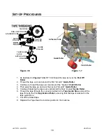
Check for proper tape threading
against threading diagram on
side plate of tape head
Re-set front tape leg length
Summary of Contents for HSD2000-ET II MIRROR
Page 1: ...HSD2000 ET II MIRROR Serial Numbers H179 or H679 XX X XXX TAPE HEAD ...
Page 2: ...UH179TW UH679TW UDH179 02 2 ...
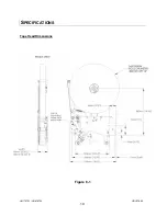
Page 10: ...UH179TW UH679TW UDH179 02 10 SPECIFICATIONS UUUTape Head Dimensions Figure 6 1 ...
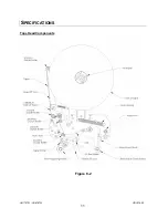
Page 11: ...UH179TW UH679TW UDH179 02 11 SPECIFICATIONS UUUTape Head Components Figure 6 2 ...
Page 41: ...41 THIS PAGE INTENTIONALLY BLANK ...
Page 42: ...6 12 3 4 8 9 1 10 11 2 5 7 42 ...
Page 44: ...7 8 9 11 6 12 7 8 7 8 9 10 3 5 2 4 1 44 MAIN FRAME ...
Page 46: ...1 2 3 4 5 46 FRONT COVER FRAME ...
Page 48: ...3 5 6 4 1 2 48 REAR COVER FRAME ...
Page 50: ... 50 REAR ARM ...
Page 52: ...11 1 15 13 14 10 2 4 5 6 9 12 8 2 3 7 13 13 10 8 CLUTCH ASSEMBLY ...
Page 54: ... 54 MANDREL ASSEMBLY ...
Page 56: ... 56 PEEL OFF ARM ASSEMBLY ...
Page 58: ... 58 LINK ASSEMBLY ...
Page 60: ...18 13 17 15 4 3 12 14 16 9 8 7 7 9 3 6 10 5 11 1 2 5 19 20 60 FRONT ARM ...
Page 62: ...1 8 9 4 7 6 9 5 2 10 3 11 62 TAPE SHOE ASSEMBLY ...
Page 64: ... 64 KNIFE ARM ...
Page 66: ... 66 REPULSIVE PIVOT ASSEMBLY ...

