UH179TW
/
UH679TW
UDH179-02
33
P
REVENTIVE
M
AINTENANCE
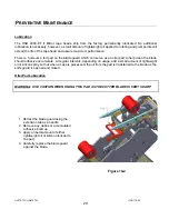
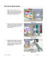
3. Remove the spring barrel from over
lapping position as shown in Figure 10-9.
Remove any broken particle from the
spring guide. Install new compression
spring into the captive position.
Figure 10-9
4. Press the spring barrel against the spring
mandrel until it is ready to slide back on
the short shaft. See Figure 10-10. Move
the whole sub assembly back to its
original position.
Figure 10-10
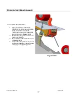
5. Reinsert retaining rings to their grooves.
Should the 12 mm retaining ring brake
(right one on Figure 10-11), the shaft
needs to be freed to replace it. Calibrate
spring pressure with the M6 nuts as
described earlier.
Figure 10-11
Snap Rings
Summary of Contents for HSD2000-ET II MIRROR
Page 1: ...HSD2000 ET II MIRROR Serial Numbers H179 or H679 XX X XXX TAPE HEAD ...
Page 2: ...UH179TW UH679TW UDH179 02 2 ...
Page 10: ...UH179TW UH679TW UDH179 02 10 SPECIFICATIONS UUUTape Head Dimensions Figure 6 1 ...
Page 11: ...UH179TW UH679TW UDH179 02 11 SPECIFICATIONS UUUTape Head Components Figure 6 2 ...
Page 41: ...41 THIS PAGE INTENTIONALLY BLANK ...
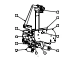
Page 42: ...6 12 3 4 8 9 1 10 11 2 5 7 42 ...
Page 44: ...7 8 9 11 6 12 7 8 7 8 9 10 3 5 2 4 1 44 MAIN FRAME ...
Page 46: ...1 2 3 4 5 46 FRONT COVER FRAME ...
Page 48: ...3 5 6 4 1 2 48 REAR COVER FRAME ...
Page 50: ... 50 REAR ARM ...
Page 52: ...11 1 15 13 14 10 2 4 5 6 9 12 8 2 3 7 13 13 10 8 CLUTCH ASSEMBLY ...
Page 54: ... 54 MANDREL ASSEMBLY ...
Page 56: ... 56 PEEL OFF ARM ASSEMBLY ...
Page 58: ... 58 LINK ASSEMBLY ...
Page 60: ...18 13 17 15 4 3 12 14 16 9 8 7 7 9 3 6 10 5 11 1 2 5 19 20 60 FRONT ARM ...
Page 62: ...1 8 9 4 7 6 9 5 2 10 3 11 62 TAPE SHOE ASSEMBLY ...
Page 64: ... 64 KNIFE ARM ...
Page 66: ... 66 REPULSIVE PIVOT ASSEMBLY ...

