background image

1

8

9

4

7

6

9

5

2 10

3 11

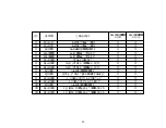
62

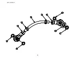
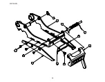
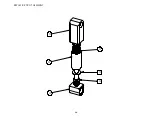
TAPE SHOE ASSEMBLY

Summary of Contents for HSD2000-ET II MIRROR

Page 1: ...HSD2000 ET II MIRROR Serial Numbers H179 or H679 XX X XXX TAPE HEAD ...

Page 2: ...UH179TW UH679TW UDH179 02 2 ...

Page 3: ...LoadingUUUTTTHHH 16 HHHTUTUTUTape ThreadingUUUTTTHHH 17 HHHTUTUTUTape CenteringUUUTTTHHH 19 HHHTUTUTUTape Leg Length AdjustmentUUUTTTHHH 20 HHHTUTUTUOne Way Clutched Roller AdjustmentUUUTTTHHH 21 HHHTUTUTUMain Spring AdjustmentUUUTTTHHH 21 HHHTUTUTUMandrel Tension AdjustmentUUUTTTHHH 22 Section 8 HHHTUTUTUTroubleshootingUUUTTTHHH 23 Section 9 HHHTUTUTURecommended Spare Parts ListUUUTTTHHH 26 Secti...

Page 4: ...This information can be found on the nameplate of the side panel of the machine Interpack Technical Support is available during normal business hours Eastern Time PHONE 800 474 8273 Option 3 If you have a technical question that does not require an immediate response you may contact Interpack by fax FAX 800 462 1293 Technical support may also be contacted via email at the address below EMAIL Machs...

Page 5: ...of the problem no later than five 5 calendar days after the warranty period If Intertape is unable to repair or replace the part within a reasonable time then Intertape at its option will replace the equipment or refund the purchase price Intertape shall have no obligation to install the repaired or replacement part Intertape shall have no obligation to provide or pay for the labor required to ins...

Page 6: ...designed to apply Intertape brand pressure sensitive carton sealing tape to the top and bottom center seam of regular slotted corrugated cartons The HSD 2000 ET II Mirror is designed to upgrade most competitive case sealers Interpack can provide a variety of adapter kits to install this tape head into most case sealers ...

Page 7: ...ting and service information Only trained personnel are to operate and service Tape Head Wear safety glasses Shut off power to machine before adjusting Unplug electrical power before servicing All covers and guards must be in place before operating Stay clear of moving parts which can shear and cut Never operate the Tape Heads with the Knife Guard removed Turn electrical supply off before servicin...

Page 8: ... spring or the guard itself is being replaced Should the tape head be operated without blade guard user voids all warranty implied the manufacturer bears no responsibility for the consequences Tape head shall never be serviced while mounted in a machine Figure 5 1 Label on Figure 5 2 is visible on carton sealing machine Figure 5 2 While the tape head is processing cartons or it is in motion keep y...

Page 9: ...nd service personnel the proper method of threading a new roll of tape through the tape head More detailed information is provided in the Set Up Procedures portion of this manual Turn air and electrical supplies off before servicing the tape heads Figure 5 4 ROLLER GUIDE ROLLER CLUTCH APPLICATION TAPE GUIDE ROLLER SHOE ADHESIVE SIDE TAPE ROLL GUIDE ROLLER PEEL OFF ROLLER ...

Page 10: ...UH179TW UH679TW UDH179 02 10 SPECIFICATIONS UUUTape Head Dimensions Figure 6 1 ...

Page 11: ...UH179TW UH679TW UDH179 02 11 SPECIFICATIONS UUUTape Head Components Figure 6 2 ...

Page 12: ...ve Carton Sealing Tape 2 Tape Width For HSD 2000 ET II 2 48mm models 1 to 2 inch wide tape 36 to 48 mm For HSD 2000 ET II 3 72mm models 2 to 3 inch wide tape 60 to 72mm 3 Tape Roll Diameter Maximum of 16 inches 405 mm on a 3 inch 76 86 mm diameter core Accommodates all Intertape brand film tape machine roll lengths 4 Tape Application Leg Length Standard 2 inches 0 25 0 57 15 mm 6 3 mm 0 mm 5 Tape ...

Page 13: ...ompetitive machinery 1 The case must be positively propelled through the case sealer taking into account any void fills overfills stability factors or weight factors 2 Verify the case sizes which will be processed through the case sealer Installing Interpack HSD 2000 ET II tape heads to process very short cases may cause the tape heads to collide with each other 3 If a flight bar or lug drive syst...

Page 14: ...H3882 4 Mounting adaptors part no UPH3881 Mounting adaptors part no UPH3883 Mounting adaptors part no UPH0283 Mounting adaptors part no UPH0864 4 4 Mounting adaptors part no UPH0282 4 Main spring part no UPH1090 1 1 Main spring part no UPH1091 Main spring part no UPH0910 1 1 Knife arm spring part no UPH4665 1 1 Knife arm spring part no UPH7427 Operational manual parts list 1 1 Note After unpacking...

Page 15: ...ck or TUFflex case sealer or case erector you do not need to follow any instructions from this section If your tape heads will be installed in any other competitive machinery please review these general guidelines plus any additional instructions included with your HSD 2000 ET II tape head Location Of Mounting Adapter Holes Front Cover Figure 7 1 Rear Cover Figure 7 2 Examples Of Mounting Hardware...

Page 16: ...e head onto a sturdy flat surface 2 Move the peel off roller away from the mandrel 3 Push the roll of tape onto the mandrel with the adhesive side up refer to Threading Diagram under Tape Threading section in this manual until the core seats against the mandrel flange This ensures the tape will be aligned when feeding into the tape head 4 Replace the peel roller against the tape roll Figure 7 4 Ad...

Page 17: ...E TAPE TO AVOID PERSONNEL INJURY Tape Threading Preparation Figure 7 5 Threading the tape in the Tape Head does not require any special tools 1 Pull approximately twelve 12 inches of tape from the roll and fold in half lengthwise adhesive side to adhesive side This allows you to thread the tape without it adhering to the guide and clutch rollers inside the Tape Head 12 ...

Page 18: ...second smooth Guide Roller 5 Continue threading the tape over and behind the final knurled Guide Roller 6 Thread the tape through the cut out provided in the Tape Guide Shoe and pull the tape through the front Application Roller ensuring that the tape is retained in the tape guide shoe 7 Cut off the folded tape 8 Replace the Tape Head to its initial position in the machine Adhesive Side Guide Roll...

Page 19: ... guide the tape mandrel can be adjusted in or out to correct this Loosen the M18 inverse jam nut on the rear of the mandrel as shown in Figure 7 8 with a 10 mm allen key Figure 7 8 Adjust the shaft in or out as required using a flat screwdriver as illustrated in Figure 7 9 When the tape is centered tighten the jam nut Figure 7 9 ...

Page 20: ...n stamped on the rear plate for a shorter tape leg Conversely bring the bottom screw towards the plus sign for a longer tape leg Re tighten both Flat Head Cap Screws Figure 7 10 Rear Tape Leg To adjust the tape leg length on the trailing end of the box both chrome knife arm extension brackets must be re positioned Unscrew the three 3 Flat Head Cap Screws on each knife arm extension using a 2 5 mm ...

Page 21: ...UUMain Spring Adjustment The main spring tension is set at the factory This setting should be optimal for most applications Environments where a different setting is desirable would be 1 Void filled cases would need a lighter wipe down pressure 2 Overfilled cases might require additional wipe down pressure 3 Double wall corrugated might need additional wipe down pressure to overcome the memory of ...

Page 22: ...t be required for the following reasons 1 Larger than 1000yd 914m are used 2 Tape head is installed on faster line speeds 3 The tape roll continues to over spin more than turn after the case leaves the tape head Should a change in mandrel tension be required follow these steps 1 Observe the rotation of a full tape roll as a case processes 2 Should the tape roll continue to rotate more than turn af...

Page 23: ... clutched roller needs adjusting Replace blade Refer to preventive maintenance section for details Replace knife spring Refer to preventive maintenance section for details Slightly increase the tension on the one way clutched roller Tape Leg UUUin the tape headUUU folds up on itself Strong air circulation fan is in the vicinity Spring loaded tape leg stiffener is out of position Redirect airflow a...

Page 24: ...d is difficult Cutter blade is dull Remove any adhesive build up with silicon spray Disassembly any non free spinning rollers and remove any adhesive build up on shafts Re set mandrel tension Disassemble mandrel assembly and check for any dust or adhesive build up Re set clutch roller tension Rethread tape through the clutch roller assembly eliminating the upper roller Replace blade Front tape leg...

Page 25: ...f the tape Tape threaded incorrectly Tape leg length misadjusted Follow corrective action in Tape Flagging section above Check for proper tape threading against threading diagram on side plate of tape head Re set front tape leg length Rear tape leg too long Tape threaded incorrectly Tape leg length misadjusted Check for proper tape threading against threading diagram on side plate of tape head Re ...

Page 26: ...re parts kits are also referenced should individual components need to be ordered HSD 2000 ET II 2 Wide Spare Parts Kit UH1002 Parts Contained in UH 1002 Spare Parts Kit MODEL NUMBER DESCRIPTION ITEM NUMBER QUANTITY SS Cut Off Blade 48mm NC UPH0193 1 Roller Shell ETM UPH0775 2 SS Ext Spring UPH0910 1 SS Main Spring ETM 080 UPM1091 1 Brush ETM UPH3655 1 Comp Spring UPH4665 1 Torsion Spring SS UPH91...

Page 27: ...H 1003 Parts Contained in UH 1003 Spare Parts Kit MODEL NUMBER DESCRIPTION ITEM NUMBER QUANTITY SS Cut Off Blade 75mm NC UPH0271 1 SS Ext Spring UPH0910 1 Roller shell ETM 3 UPH0966 2 SS Main Spring ETM 080 UPH1091 1 Brush ETM II 3 UPH3674 1 Compression Spring UPH4665 1 SS Torsion Spring UPH9195 1 ...

Page 28: ...and prolong the life of the tape head Please review the illustration and chart below for information regarding tape head maintenance UUUKnife Blade Replacement The knife blade is made from hardened steel and should provide a minimum of 250 000 cycles before replacement The cut off blade is locked in position with two 2 M5 Button Head Cap Screws To replace the cut off blade 1 Loosen both screws wit...

Page 29: ...ean the blade should adhesive accumulate At regular intervals depending on usage add a small amount of lightweight oil or silicon spray so that when a case is processed the oil from the pad is transferred to the blade as the knife guard is opened and closed UUUOiler Pad Lubrication UUUWARNINGUUU USE CAUTION WHEN OILING THIS PAD AS THE CUTTER BLADE IS VERY SHARP 1 Retract the blade guard using the ...

Page 30: ...roller from its mounting hub Figure 10 3 Installing The New Urethane Roller 1 Feed the new roller onto the end of the hub edge without the raised shoulder 2 Press the new roller all the way down to the end of the hub and against the raised shoulder 3 Reinstall the roller hub onto the roller arm shaft with the raised shoulder away from you 4 Replace the spring washer and flat washer 5 Replace the s...

Page 31: ...ining ring in the middle 4 Stretch the spring over rear arms spring retainer ring using either needle nose pliers or your finger Hook the loop securely into the retainers groove Figure 10 5 Knife Arm Spring Adjustment Should the Knife Arm Cutting Force need to be adjusted follow the procedure below 1 To increase the force using a 10mm open end wrench turn the 6mm nut clockwise until desired pressu...

Page 32: ...ange it is as follows 1 Carefully open the snap ring with a plier and slide it up on the cross shaft Remove the snap ring attached to the knife arm assembly Ware safety glasses while working with retaining rings Figure 10 7 2 Slide off the repulsive pivot assembly from current position as shown in Figure 10 8 Figure 10 8 Snap Rings ...

Page 33: ...gure 10 9 4 Press the spring barrel against the spring mandrel until it is ready to slide back on the short shaft See Figure 10 10 Move the whole sub assembly back to its original position Figure 10 10 5 Reinsert retaining rings to their grooves Should the 12 mm retaining ring brake right one on Figure 10 11 the shaft needs to be freed to replace it Calibrate spring pressure with the M6 nuts as de...

Page 34: ...red with loctite and may require applied heat prior to removal 1 Using two 2mm hexagonal keys as shown remove one of the flathead countersink screws by applying force on both hexagonal key in an attempt to remove each screw 2 Once one of the screws breaks fee only continue to remove that screw 3 Leave the remaining flathead countersink screw that did not yield attached to the cross shaft Figure 10...

Page 35: ...W UH679TW UDH179 02 35 PREVENTIVE MAINTENANCE Carefully slide out the shaft from the end of the shaft that contains the remaining flathead countersink screw Figure 10 14 Remove the broken spring Figure 10 15 ...

Page 36: ...10 16 2 Note which leg of the spring should lie behind the cutter blade mounting plate 3 Note which leg of the spring should wrap around the front of the knife guard Figure 10 16 Insert the cross shaft through the knife arm knife guard and knife guard spring as shown in Figure 10 17 Figure 10 17 Behind The Cutter Blade In Front Of Knife Guard ...

Page 37: ...ew and fasten to the end of the cross shaft Tighten using two 2mm hexagonal keys as shown in Figure 10 18 2 Rotate the knife guard to make sure there is no binding 3 Re install the cutter blade as shown in Figure 10 12 4 Inspect the oiler pad to make sure it is securely fastened Clean the pad and apply some lightweight oil Figure 10 18 ...

Page 38: ... can better conform to the irregularities of the top of the case such as over fills void fills and the wash board effect of thinner walled corrugated Over time this brush can become distorted or worn and should be replaced Wipe Down Brush Replacement 1 Remove 2 M5 flathead countersink screws Item 1 from the operator side panel using a 3 mm hex key 2 Remove the brush Item 2 3 Install new brush with...

Page 39: ... build up Solvent Cleaner X Knurled PTFE Coated Guide Roller Rotation should be slightly restricted by Belville washer Disassemble and remove any adhesive build up if excessive restriction is detected Solvent Cleaner X Front Red Wipe Down RollersRotation should be slightly restricted by Belville washer Disassemble and remove any adhesive build up if excessive restriction is detected Solvent Cleane...

Page 40: ...2 Main Frame Sub Assembly 44 Front Cover Frame Sub Assembly 46 Rear Cover Frame Sub Assembly 48 Rear Arm Assembly 50 Clutch Assembly 52 Mandrel Assembly 54 Peel Off Arm Assembly 56 Link Assembly 58 Front Arm Assembly 60 Tape Shoe Assembly 62 Knife Arm Assembly 64 Repulsive Pivot Assembly 66 ...

Page 41: ...41 THIS PAGE INTENTIONALLY BLANK ...

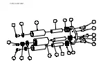
Page 42: ...6 12 3 4 8 9 1 10 11 2 5 7 42 ...

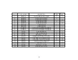
Page 43: ... USH1071 CLUTCH ASS Y 48 MIRROR 1 5 USH1072 CLUTCH ASS Y 72 MIRROR 1 6 USH1008 MANDREL ASS Y ET TW 48 1 6 USH1009 MANDREL ASS Y ET TW 72 1 7 USH0935 PEEL OFF ASS Y 48 MIRROR 1 7 USH0936 PEEL OFF ARM ASS Y 75 MIRROR 1 8 USH0939 LINK ASS Y ET II 1 1 9 USH1064 FRONT ARM MIRROR 1 9 USH1065 FRONT ARM 72 MIRROR 1 10 USH1062 KNIFE ARM 2 ET 2 5 MIRROR 1 10 USH1063 KNIFE ARM 3 ET 2 5 MIRROR 1 11 USH1057 RE...

Page 44: ...7 8 9 11 6 12 7 8 7 8 9 10 3 5 2 4 1 44 MAIN FRAME ...

Page 45: ...ACER BAR 1 4 UPH3665 SPACER BAR 3 5 UPH7259 SPACER BAR 1 6 UPH3636 ARMS PIVOT SHAFT ETM II 3 6 UPH3664 ARMS PIVOT SHAFT ETM II 3 7 UPH0872 STOP RETAINER ETM 3 3 8 UPH133 STOP URETHANE KNIFE ARM 3 3 9 UF5800 FLAT WASHER DIA 5 5 x 20 4 THK 2 2 10 UF5404 FHCS M5 0 8 x 16 mm 10 10 11 UF6337 F W PTFE 12 5 x 20 x 0 29 mm 4 4 12 UF6336 F W PTFE 13 x 19 x 1 mm 4 4 45 ...

Page 46: ...1 2 3 4 5 46 FRONT COVER FRAME ...

Page 47: ...ITEM PART DESCRIPTION USH1068 QTY 1 UPH9108 FRONT COVER FRAME MIRROR 1 2 UF5404 FHCS M5 0 8 x 16 mm 2 3 UF5400 FHCS M5 0 8 x 12 mm 1 4 UPH133 STOP URETHANE KNIFE ARM 1 5 UPH0872 STOP RETAINER ETM 1 47 ...

Page 48: ...3 5 6 4 1 2 48 REAR COVER FRAME ...

Page 49: ... USH1069 2 QTY USH1070 3 QTY 1 UPH9104 REAR COVER FRAME MIRROR 1 1 2 UF5404 FHCS M5 0 8 x 16 mm 8 8 3 UPH3655 BRUSH 2 1 3 UPH3674 BRUSH 3 1 4 UPH3640 RETAINER MAIN SPRING 2 1 4 UPH3666 RETAINER MAIN SPRING 3 1 5 UF6303 EXT RETAINING RING 9mm 1 1 6 UPH0863 MAIN SPRING RETAINER SLEEVE 1 1 49 ...

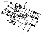
Page 50: ... 50 REAR ARM ...

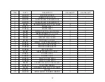
Page 51: ...7 1 5 0 1 635 1 83 5 7 1 5 0 1 635 1 83 5 7 1 5 0 1 635 1 83 5 7 1 5 0 1 635 1 83 1 6 7 70 83 0 1 635 1 5 7 1 5 6 9 83 52 5 6 83 52 5 6 8 7 21 PP 8 7HIORQ PP 8 7 5 7 1 1 5 1 PP 8 5 7 1 1 5 1 25 PP 6 7 8 66 5 7 1 1 5 1 25 PP 6 7 8 5 7 1 1 5 1 25 PP 6 7 8 66 5 7 1 1 5 1 PP 6 7 8 6 0 PP 8 66 6 0 PP 8 6 0 8 66 6 0 8 6 0 PP 8 66 6 0 PP 8 7 5867 6 5 8 66 7 5867 6 5 83 63 5 8 5 7 1 1 5 1 PP 66 51 ...

Page 52: ...11 1 15 13 14 10 2 4 5 6 9 12 8 2 3 7 13 13 10 8 CLUTCH ASSEMBLY ...

Page 53: ...54 CLUTCH SHAFT 1 5 UAH0220 CLUTCH W BEARINGS 48 MIRROR 1 5 UAH0221 CLUTCH W BEARINGS 72 MIRROR 1 6 UF6346 FW M8 NARROW 1 1 7 UF6391 F W 6 x 16 x 1 mm 2 2 8 UF1195 BHCS M6 1 x 12 mm 2 2 9 UF1870 BELLEVILLE W 0 26 x 0 5 x 036 3 3 10 UF6335 F W PTFE 12 5 x 20 x 0 55 mm 4 4 11 UF6402 F W PTFE 12 5 x 17 5 x 0 5 mm 3 3 12 UF5900 NYLON LOCK NUT M6 1 0 1 1 13 UF5402 FHCS M6 1 x 20 3 3 14 UF1042 FHCS M6 1...

Page 54: ... 54 MANDREL ASSEMBLY ...

Page 55: ...5 7 66 7 83 6 7 0 1 5 7 66 7 8 5 6 5 8 0 1 5 7 7 Z 5 1 6 8 0 1 5 7 7 Z 5 1 6 83 0 1 5 5 7 21 6 5 83 66 0 1 5 5 7 21 6 5 83 0 1 5 635 1 83 66 0 1 5 635 1 83 0 1 5 8670 17 187 83 66 0 1 5 8670 17 187 83 0 1 5 2 187 83 66 0 1 5 2 187 83 25 2 0 1 5 7 83 25 2 0 1 5 7 8 66 6 6 0 PP 8 1 21 2 187 0 8 66 1 21 2 187 0 8 6 0 PP 8 66 6 0 PP 55 ...

Page 56: ... 56 PEEL OFF ARM ASSEMBLY ...

Page 57: ...83 3 2 50 3 927 8 1 21 PP 8 6 0 PP 8 66 6 0 PP 8 6 6 0 PP 8 66 6 6 0 PP 8 6 0 PP 8 66 6 0 PP 8 6 6 0 PP 8 66 6 6 0 PP 83 8 52 5 6 7 83 8 52 5 6 7 8 6 0 PP 8 66 6 0 PP 8 PP 8 66 8 7 5867 6 5 8 66 7 5867 6 5 83 3 2 52 5 7 83 3 2 52 5 7 83 635 1 3 2 70 83 635 1 3 2 70 8 6 0 PP 8 66 6 0 PP 83 3 2 50 0 5525 83 3 2 50 66 0 5525 57 ...

Page 58: ... 58 LINK ASSEMBLY ...

Page 59: ... 7 0 3 57 6 5 37 21 86 47 83 1 52 83 52 1 5 1 PP 5 83 52 1 5 1 PP 8 0 187 0 7 8 0 187 0 8 1 21 PP 8 1 21 PP 8 1 21 6 5 59 ...

Page 60: ...18 13 17 15 4 3 12 14 16 9 8 7 7 9 3 6 10 5 11 1 2 5 19 20 60 FRONT ARM ...

Page 61: ...CS M5 0 8 x 12 mm 2 2 8 UF5404 FHCS M5 0 8 x 16 mm 1 1 9 UF1192 FHCS M6 1 x 16 mm 2 2 10 UPH0281 SPRING TAPE GUIDE ROLLER T H 1 1 11 UPH0884 TEFLON ROLLER SHAFT 48 1 11 UPH0968 TEFLON ROLLER SHAFT 72 1 12 UPH0886 LINK SHAFT ETM 1 1 13 UF1861 THRUST WASHER 12 4 x 20 x 1 1 1 14 UPH3641 ROLLER CORE 1 14 UPH3667 ROLLER CORE 1 15 UPH3643 SHAFT ROLLER ETM II 1 15 UPH3668 SHAFT ROLLER ETM II 1 16 UF6402 ...

Page 62: ...1 8 9 4 7 6 9 5 2 10 3 11 62 TAPE SHOE ASSEMBLY ...

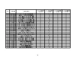
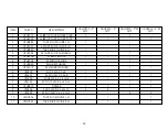
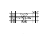
Page 63: ...GUIDE R H 1 3 UPH1032 SS TAPE SHOE GUIDE R H 1 4 UPH3706 SPRING BLADE 1 1 4 UPH3705 SS SPRING BLADE 1 1 5 UPH0880 SQARE WASHER 1 1 5 UPH1019 SS SQARE WASHER 1 1 6 UF6400 SHCS M3 0 5 x 8 1 1 6 UF6401 SS SHCS M3 0 5 x 8 1 1 7 UF5202 SHCS M3 0 5 x 6 mm 1 1 7 UF3145 SS SHCS M3 0 5 x 6 mm 1 1 8 UPH0879 FINGER 1 1 1 1 9 UF5406 FHCS M2 0 4 x 6 mm 4 4 9 UF3259 SS FHCS M2 0 4 x 6 mm 4 4 10 UPH0836 TAPE SHO...

Page 64: ... 64 KNIFE ARM ...

Page 65: ... 47 86 47 83 193 87 2 83 71 87 2 8 6 0 PP 83 6 7 8 5 83 6 7 8 5 83 7256 21 635 1 8 8 5 203 7 8 8 5 203 7 8 6 0 PP 8 5 7 1 1 5 1 25 PP 6 7 83 1 50 7 16 21 5 7 83 1 50 7 16 21 7 8 6 0 PP 8 1 50 5 1 0 5525 8 1 50 5 1 0 5525 65 ...

Page 66: ... 66 REPULSIVE PIVOT ASSEMBLY ...

Page 67: ... 7 0 3 57 6 5 37 21 86 47 86 47 8 635 1 0 1 5 9 8 635 1 0 1 5 9 66 83 635 1 8 9 83 635 1 55 9 83 203 635 1 2 21 83 203 635 1 2 66 8 0 187 0 8 66 0 187 0 8 PP 8 66 67 ...

Reviews: