background image

46 

Interference Problems 

 
Interference can come from several sources. The 
most common of these are: 
 
1)  Other nearby depth sounders operating at the 

same frequency. 

2)  Radiated interference from the boat’s electrical 

system (alternator, distributor and spark plugs) 
or from nearby equipment that radiates 
electrical noise. 

3)  Conducted interference usually occurs when 

the Ultrascan PC90 shares a 12VDC power 
lead with other noisy equipment (i.e.; bilge 
pumps, motors, refrigeration systems, 
autopilots, etc.) 

 
Interference caused by nearby depth sounders 
operating on or near the same frequency as the 
Ultrascan PC90 will typically appear as “rabbit 
tracks” that march up and down the screen.  
Reducing the gain will help minimize this problem. 
 
Radiated interference caused by the boat’s engine 
can usually be identified by observing the Ultrascan 
PC90 with both the engine running and turned off.  
If the interference disappears when the engine is 
turned off, it is safe to assume that the engine is the 
source of the interference. 
 
This type of interference can usually be eliminated 
by using the same techniques used in the 
automotive industry to eliminate interference to car 
radios, CB’s, etc.  The following actions may be 
required: 
 
1)  Reduce the Gain setting to minimize 

interference. 

2)  Make sure your boat uses resistor type spark 

plugs and plug wiring. 

3)  Install a suppressor on the center lead of the 

distributor. 

4)  Install an alternator filter to smooth the 

alternator’s output signal. 

 
Interference may also be caused by radiation from 
other nearby equipment and can be detected by 
turning off all other equipment and observing the 
Ultrascan PC90 display as each suspected source is 

turned back on.  This type of interference can 
usually be eliminated by moving the Ultrascan 
PC90 Beamformer Module away from the source 
and checking to ensure that the interfering source is 
properly grounded. 
 
Interference causing the display to be unstable, to 
pulsate or periodically change size is usually caused 
when another piece of equipment shares the same 
12 VDC power leads from the battery.  This 
problem is especially severe when equipment 
requiring large current surges (i.e.; autopilots, 
refrigerators, or bilge pumps) share the same power 
leads.  Minimize this type of interference by 
running the Ultrascan PC90’s 12VDC power leads, 
or those of the interfering equipment, directly to the 
battery. 
 
Alternatively, you may find it helpful to install a 
separate dedicated power supply battery that is used 
only to run your electronic gear (e.g.; fishfinders, 
VHF radios, radar units, etc.).  If your unit shuts off 
during low voltage situations, such as when 
cranking your engine starter, you may want to 
install an isolator switch with an “A/B” type of 
battery system.  An “A/B” system allows you to run 
your electronic gear on one battery, while the starter 
and alternator are hooked up to the other battery. 
 
Your authorized marine electronics dealer is 
familiar with the methods of reducing electrical 
interference and is qualified to assist you should a 
problem persist. 


Summary of Contents for ULTRASCAN PC90

Page 1: ......

Page 2: ...PC90 Forward Scanning Sonar and your satisfaction is very important to us We welcome any comments or suggestions that you might have about this equipment It is very important that you complete and re...

Page 3: ...ransducer Installation 13 Selecting a Location 13 Attaching the Bracket 13 Bracket Axel Assembly 15 Beamformer Module Installation 16 Software Installation 17 Connecting to Computer 18 Computer Networ...

Page 4: ...Depth Window 32 Using the Alarm 33 Adjusting the Depth Tracker 34 Surface Masking 34 Threshold 34 Saving Data with Screen Capture 35 5 Advanced Operation 36 Working with NMEA Navigation 36 Logging De...

Page 5: ...5 Specifications 47 How To Obtain Service 51 9 Advanced Networking Information 48 Warranty 55...

Page 6: ...ides a Limited Warranty on the Ul trascan PC90 Forward Scanning Sonar Please read this warranty reprinted at the back of this manual and closely follow its terms and conditions should your Ultrascan P...

Page 7: ...ormer Module D1 0400 001 Ethernet Cable 10 length 04 1107 00R 12VDC Power Supply Cable 04 1106 00R Ultrascan PC90 Software CD 52 1004 001 Operation Manual 25 4018 000 Transducer Options Description Pa...

Page 8: ...ally transparent DO NOT allow any solvents i e gasoline acetone to come in contact with the transducer s as this may dissolve the plastic housing In the single thru hull configuration all of the trans...

Page 9: ...unt of acoustic noise air bubbles or turbulence caused by the boat s movement The transducer should not be located nearby or especially directly behind the propeller Choose a location where the transd...

Page 10: ...leading edge of the keel and sometimes faired into the keel As this location may be where the sling rests when hauling the boat the transducer may be placed on either side of the hull with the foremo...

Page 11: ...ad it through the hole into the inside of the hull Apply a 1 8 thick layer of sealant on the upper flat surface of the transducer bronze alignment pin and fairing block if used From the outside of the...

Page 12: ...lted off the vertical at the same angle as the dead rise so most thru hull installations will require a fairing block to insure the transducer is mounted properly If you re installation requires a fai...

Page 13: ...or the water force exceeds the resistance of the bracket the transducer automatically kicks up and becomes non operational The bracket does not automatically reset at lower speeds The transducer must...

Page 14: ...nsducer s stainless mounting ears Make sure the spray shield is orientated as shown in sketch below Then assemble the stainless kick up bracket to the transducers using the 4 screws washers and lock n...

Page 15: ...lace align the long stainless steel spacer with the mounting holes of the mounting bracket and slide the axle in place through the spacer 5 Place one small stainless steel spacer against the transduce...

Page 16: ...con nected to your ships positive battery sup ply and the black wire to the negative of your boat s battery To prevent accidental damage it s recommended that an inline slow blow 2 Amp fuse also be i...

Page 17: ...indows XP Vista or Windows 7 Take the following steps to install Ultrascan PC90 on your computer 1 Exit all programs that are currently running 2 Insert the Ultrascan PC90 CD Disk into your computer s...

Page 18: ...ND SHARING CENTER Then click on MANAGE NETWORK CONNECTONS Right click on the Network Connection that needs to be changed usually the local area connection and then select PROPERTIES as shown at top le...

Page 19: ...sly set to 192 168 1 3 Press OK to close the beamformer settings window The Orange light on the Ultrascan Beamformer Module should light when a proper connection between the Beam former and PC is made...

Page 20: ...the gain until you begin to see noise then decrease the setting by one see p 30 Defaults The default settings for many of the Ultrascan PC90 features are shown in the table at left Hard defaults are a...

Page 21: ...scanning beams at different distances from the boat The Ultrascan PC90 will generally image features within the shaded areas The Ultrascan PC90 horizontal scan is oriented approximately ten degrees do...

Page 22: ...isplays the software version number and Alarm Reset which turns off the depth alarm after it has been triggered see p 31 The Toolbar also includes three digital data displays including from left to ri...

Page 23: ...iately begin to collect and display data in Live Mode If a recording is being viewed the unit will be in the Playback Mode Use the File Menu to switch between Playback and Live modes Playback Mode In...

Page 24: ...sducer is tilted forward a level bottom will appear to be getting shallower at greater distances If it is tilted back a level bottom will appear to be getting deeper Level Adjustment In case the verti...

Page 25: ...nting slightly in the starboard direction If the target is offset to the port by 7 degrees the Transducer Align correction should be 7 degrees Stbd If the target appears off to the right Stbd adjust t...

Page 26: ...can be viewed in one of three color schemes Normal a color palette varying from light blue through red on a black background which is useful for operation in normal daytime conditions Sunny a gray sc...

Page 27: ...27 Horizontal Display Vertical Display Downlooker Display Vertical Split Screen Display DISPLAY MODES...

Page 28: ...ugh a maximum of 90 degrees in a sector centered about the boat s heading and tilted downward from horizontal by about 10 degrees see figure at left center The horizontal scan is shown with the transd...

Page 29: ...f the window The downlooker data occupies one quarter of the horizontal dimension of the window and the vertical scan occupies the remainder of the space Both portions of the display are equivalent in...

Page 30: ...rascan PC90 allows you to choose from 32 different Gain levels numbered from 1 to 32 The default level is 16 Select the Gain by sliding the pointer on the Gain bar Level 1 provides the smallest amount...

Page 31: ...o keep the bottom within the center three quarters of the range scale If Ultrascan PC90 cannot find the bottom it will step through the Ranges until the bottom is found It is possible to make manual a...

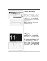
Page 32: ...to the right Depth Window In addition to the four scanning sonar displays Ul trascan PC90 includes a separate depth window that can be moved and resized to fill any portion of the screen Open the wind...

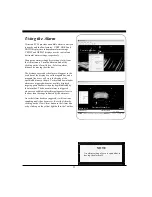
Page 33: ...a solid magenta bar and a magenta line or arc will cross the display at the specified distance or depth Vertical and downlooker alarms are triggered whenever a solidly displayed target appears shallo...

Page 34: ...rface Masking feature allows you to specify a range near the water surface in which the depth tracker will ignore any incoming returns The default Surface Masking is off Surface Masking is useful if t...

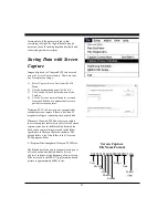
Page 35: ...requested or scheduled screen capture if there is less than 20 megabytes of space remaining on your hard disk Whenever Ultrascan PC90 does a screen capture the screen capture indicator to the left of...

Page 36: ...ation box on the toolbar If no data is detected coming from the serial or USB port a series of dashes will be dis played in the navigation box A blank navigation box indicates that NMEA 0183 input is...

Page 37: ...and the year all in UTC and the local zone hours and minutes Atlantic Standard Time is local zone 05 hours 00 minutes Once you have selected the depth log format select a depth log frequency interval...

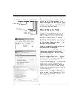
Page 38: ...o recording of the raw data is available the record button will be a bright red color To start the recording depress the RED record button When recording the bottom toolbar will say RE CORDING and the...

Page 39: ...C90 To gain the most information about your system be sure that the Ultrascan PC90 hardware is connected to your computer and turned on before selecting Run Diagnostics from the File menu To save the...

Page 40: ...e it took to receive the return echo it can determine the location of the object or bottom that created the return echo As the Ultrascan PC90 sequentially steps through the scan sector the computer s...

Page 41: ...elobe Effect The Ultrascan PC90 s transducer like all transducers does not form a perfect beam of acoustic energy Some of the energy is contained in areas outside of the main beam called sidelobes see...

Page 42: ...cts of surface noise clutter when the water is choppy and to allow easier mounting of the transducer to the transom of smaller boats Imaging the Bottom As the acoustic beam is projected away from the...

Page 43: ...p in the bottom echoes Forward Imaging Capabilities If the horizontal range setting is greater than the forward distance to the bottom the Ultrascan PC90 can detect targets at distances beyond where t...

Page 44: ...your 12 VDC power source If the polarity is correct check with the Technical Service Department at 408 477 4944 3 In order to protect your transducer from water damage we suggest painting it with a w...

Page 45: ...dule and your computer and that the Beamformer Module is on Check to see that the proper I P address is selected Select Run Live from the File menu Screen remains blank in PLAYBACK Mode Ultrascan PC90...

Page 46: ...ternator filter to smooth the alternator s output signal Interference may also be caused by radiation from other nearby equipment and can be detected by turning off all other equipment and observing t...

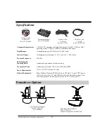
Page 47: ...VISTA or Win7 operating system CD drive 10 MB available hard disk space Depth Ranges Overlapping ranges 0 to 30 ft min 0 to 800 ft max Forward Ranges Overlapping forward ranges 0 50 ft min to 0 1 200...

Page 48: ...0 Research Park Drive Suite 140 Soquel CA 95073 In addition to speed your repair please fill out the following tear this page out of the manual or photocopy it and tape it to your unit for our technic...

Page 49: ...For example if you configure your PC s network card for IP address 192 168 1 3 the Ultrascan beamformer must have the same subnet numbers the first three sets of numbers 192 168 1 but it can not have...

Page 50: ...address If you forget the new IP address you will not be able to connect to a PC or network and may have to return the red beamformer box to Interphase to reset to the factory default IP address To a...

Page 51: ...51 Click here to make changes should appear in your browser If you make changes to any of the Ultrascan beamformer s network settings you will have to reboot the beamformer by cycling power off on...

Page 52: ...bnet use the ipconfig DOS command see page 49 When connecting to a network hub or switch a crossover Ethernet cable is usually required to connect between the Ultrascan beamformer and the hub or switc...

Page 53: ...53 This Page for Notes...

Page 54: ...54 This Page for Notes...

Page 55: ...ich have been repaired or altered outside the Interphase factory Any costs incurred with transducer replacement are specifically excluded from this warranty other than the cost of the transducer itsel...

Page 56: ...56...

Reviews: