


45
User Manual
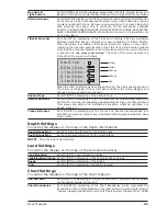
Output Sentences
The chart plotter allows customizing the NMEA-0183 sentence transmitted on
each port. Each port can transmit a different set of sentences among: GLL, VTG,
BOD, XTE, BWC, RMA, RMB, RMC, APB, WCV, GGA, HSC, HDG:
[MENU] + "SETUP" + [ENTER] + "Input/Output" + [ENTER] + "Port 1/2/3
(
CM 11CV+/11CVS+
: ports
4/5
too)
Output Sentences" + [ENTER]
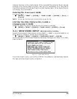
NMEA Data Input
Allows the chart plotter to act as a computer terminal and display the incoming
data exactly as it is received:
[MENU] + "SETUP" + [ENTER] + "Input/Output" + [ENTER] + "NMEA Data
Input" + [ENTER]
CM 169CS/169CSi/7Mi/7Ci/7MX/7CXS:
Cable Wiring page
Shows a window containing the cable wiring related to the quick disconnect bracket:
[MENU] + "SETUP" + [ENTER] + "Input/Output" + [ENTER] + "Cable Wiring"
+ [ENTER]
CM V6/V6i/11CV+/11CVS+:
Power I/O Cable Wiring page
Shows a window containing the Power I/O cable wiring.
[MENU] + "SETUP" + [ENTER] + "Input/Output" + [ENTER] + "Power I/O
Cable Wiring" + [ENTER]
CM V6/11CV+/11CVS+:
GPS Cable Wiring page
Shows a window containing the GPS cable wiring.
[MENU] + "SETUP" + [ENTER] + "Input/Output" + [ENTER] + "GPS Cable
Wiring" + [ENTER]
CM 11CV+/11CVS+:
AUX IN I/O Cable Wiring page
Shows a window containing the interface cable wiring.
[MENU] + "SETUP" + [ENTER] + "Input/Output" + [ENTER] + "AUX IN I/O
Cable Wiring" + [ENTER]
Send/Receive Routes & Marks
Sets the desired port used for transferring User Points and Routes functions:
[MENU] + "SETUP" + [ENTER] + "Input/Output" + [ENTER] + "Send/Rec
Routes & Marks" + [ENTER] + "Port 1/2/3
(
CM 11CV+/11CVS+
: ports
4/5
too)
" + [ENTER]
C-Link menu
Select the Primary or Secondary Station (see the dedicated Chapter):
[MENU] + "SETUP" + [ENTER] + "Input/Output" + [ENTER] + "C-LINK" +
[ENTER] + "Secondary Station/Primary Station" + [ENTER]
CM 11CV+/11CVS+:
External Output
Sets the External Output:
[MENU] + "SETUP" + [ENTER] + "Input/Output" + [ENTER] + "EXTERNAL
OUTPUT" + [ENTER]
Then choose your preferred setting among External Alarm (when activated, this
pin goes to GND level. It is used to command an external buzzer), Radar Power
On (it is command switch for the Radar. It must be used in conjunction with the
Radar Junction box device) and Off.
Summary of Contents for Chart Master 169CSI
Page 14: ...16 User Manual...
Page 34: ...36 User Manual...
Page 54: ...56 User Manual...
Page 72: ...74 User Manual...
Page 78: ...80 User Manual...
Page 81: ...83 User Manual INSTALLATION AND REMOVING EXTERNAL WIRING...
Page 84: ...86 User Manual...
Page 86: ...88 User Manual Dimensions...


