

52
User Manual
nation position and activate the navigation to it.
If the Master is navigating to a Route, the Slave will show the Route Leg com-
posed by the Destination and the Waypoint after the Destination (Next Waypoint)
and activate the navigation to it.
Any variation to the current C-Link navigation data will be transferred from the
Master to the Slave.
The Slave will be provided with a few dedicated pages to show the C-Link naviga-
tion data received from the Master.
Operations
Introductive elements
It is important remark, once more, that this function does not transfer the whole
route but just the information relative to the navigation. Such information will be
removed from the Slave Chart Plotter as soon as the navigation is terminated.
C-Link navigation data is exchanged by using two NMEA-0183 C-MAP proprietary
sentences: $PCMPN,1 and $PCMPN,2.
When the navigation is activated on the Master, it starts outputting the C-Link
navigation data. If the Slave is connected, all C-Link navigation data received are
stored in its memory and the navigation is started.
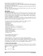
The information sent by the Master consists of the following values:
- Navigation mode (To Single Destination / to a Route )
- Route Name (*)
- Destination ID
- Destination Position
- Next Waypoint ID (*)
- Range from Destination to next Waypoint (*)
- Bearing from Destination to next Waypoint (*)
- Route Length (*)
- Distance from Destination to Last Route Waypoint (*)
- Remaining Route Legs (*)
- Planned Cruising Speed
- Average Fuel Consumption
- Initial Fuel Load
C-Link navigation data can refer to:
- Single Destination navigation
- Route Following navigation.
Values identified by (*) are sent only for Route Following navigation.
The Destination Icon, Navigation leg (Fix Position to Destination), the Next Way-
point Icon and all other relevant C-Link navigation data will be shown on the Slave
chart plotter. Any variation of the C-Link navigation data on the Master will be
communicated to the Slave so to keep data aligned on both devices.
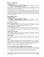
C-Link serial connection
The two chart plotters should be connected via serial ports. Any of the available
ports can be used, the software will recognize automatically the serial ports used.
A typical connection is as follows:
CP1
CP2
TX
—————> RX
RX
<————— TX
GND
<————> GND
Summary of Contents for Chart Master 169CSI
Page 14: ...16 User Manual...
Page 34: ...36 User Manual...
Page 54: ...56 User Manual...
Page 72: ...74 User Manual...
Page 78: ...80 User Manual...
Page 81: ...83 User Manual INSTALLATION AND REMOVING EXTERNAL WIRING...
Page 84: ...86 User Manual...
Page 86: ...88 User Manual Dimensions...