14
Transom Mounting Location
The main source of vessel acoustic noise is the propeller.
It is very important to position the transducers to
minimize noise pickup and provide as clear a view as
possible of the water ahead of the boat. Study the hull
shape of the vessel carefully to determine the best
transducer mounting location. To achieve optimal
operation the transducers should be mounted in a spot
which:
*
Minimizes acoustic noise reception.
*
Minimizes the chance that aerated water
will flow across the transducer’s frontal
nose area.
*
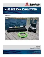
Optimizes the transducers view of the area
ahead and directly below the boat. (See
diagram below, bottom left)
The transducers can be installed on either side of an
outboard or inboard/outboard engine, or between twin
outboards. For single engine installations, normally 18”
to 24” outboard of the propeller center line is acceptable
and the down stroke side of the propeller is preferred.
Choose a location where water flow is smoothest. For
dual engine installation, just off the center line is usually
acceptable.
Because the transducers rotate back and upwards when
the brackets kick up, they must be mounted in a location
where there is sufficient clearance and headroom to allow
the full kick-up.
Attaching the Transducer and Spray Shield
to the Bracket
Locate the stainless spray shield inside the transducer’s
stainless mounting ears. Make sure spray shield is
orientated as shown in sketch on following page.
Then, assemble the stainless kick-up bracket to the
transducers using the 4 screws, washers and lock nuts
provided. The bracket arms must be mounted outside the
stainless steel mounting ears of the transducer. Do not
fully tighten the lock nuts at this time.
Position the transducer so that it is perpendicular from
side to side and make sure the rounded shaped area is
pointed towards the front of the boat.
Mounting the Transducer to the Boa
t
After you have selected the optimum mounting location
and have assembled the mounting bracket to the
Boat’s Hull
Tramsom Mount Locations
18 - 24"
Cables
Twin Outboards
Transducer
Cable
Summary of Contents for Color Twinscope
Page 1: ...1 OPERATION MANUAL INTERPHASE INTERPHASE TWINSCOPE...
Page 83: ...83 Notes...
Page 84: ...84...
Page 86: ...86...
Page 88: ...88...