


22
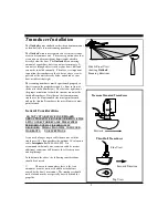
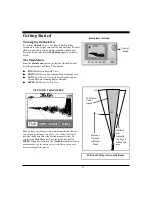
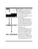
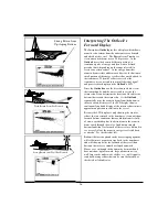
Down View
(Conventional down looking)
The
Outlook’s phased array transducer can be electronically
steered to look directly below the boat. In this mode the
Outlook LCD display will show a picture exactly like
conventional fixed beam down-looking fish finders. When in
this mode, the
Outlook offers a full range of sophisticated
features which are found on advanced conventional depth
sounders such as split screen zoom, bottom lock, a shallow
depth alarm, and bottom hardness (white-line).
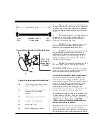
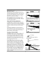
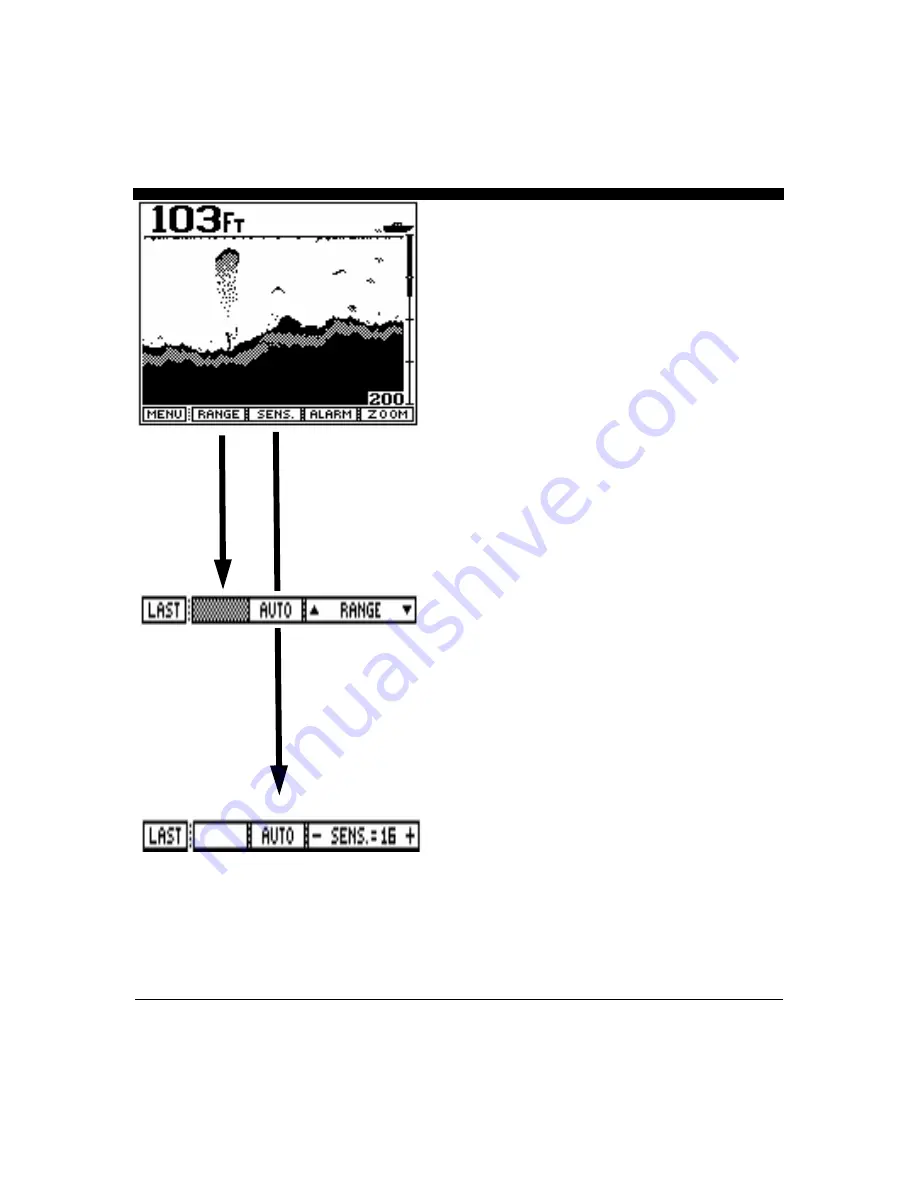
From the
Main menu select the DOWN button to bring up the
menu showing the features and adjustments for this view. The
display should be similar to that at left.
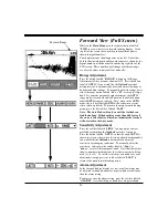
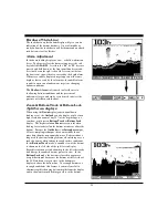
Range Adjustment
Press the button labeled
RANGE to bring up the Range
Adjustment soft key menu. Press the button labeled
AUTO if
you would like the
Outlook’s internal microprocessor to
automatically select and adjust the depth range as bottom
conditions change. To manually adjust the depth, press either
the range button labeled " " or " ". If you make a manual
depth adjustment, the
AUTO range mode is turned off and will
remain off until the button labeled
AUTO is again selected.
Note: when in the
AUTO mode, the soft key labeled "AUTO"
will be shown in reverse video (white on black). To return to
the main forward looking menu, press the soft key labeled
"
LAST". (To return to the Main menu press the soft key
labeled "
MENU")
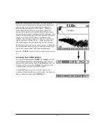
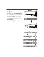
Sensitivity Adjustment
Press the soft key labeled "
SENS." (for sensitivity) to bring up
the choices available for adjusting the
Outlook's receiver
sensitivity. Press the button labeled "
AUTO" so that the word
AUTO is shown in reverse video (white letters on a black
background) if you would like the
Outlook to automatically
adjust its sensitivity for changing conditions. To manually
adjust the sensitivity, press the button labeled “
- Sens” or
“
Sens.+” to increase or decrease the receiver gain. Note that
the soft key shows a number which indicates the relative
sensitivity being used (+1 to +32). When you choose to
manually adjust the sensitivity, the
Outlook turns off the
AUTO sensitivity mode and it will remain off until the AUTO
soft key is again selected. Note: when
AUTO mode is turned
on the word will be displayed in reverse video (white letters
on a black background). To exit the sensitivity menu and save
your adjustments simply press the soft key labeled “
LAST” to
return to the main forward looking menu.
Summary of Contents for Outlook
Page 1: ...1 OPERATION MANUAL...
Page 36: ...36...


