


28
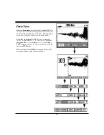
To minimize the sidelobe effect, sensitivity should be
reduced.
However, in some situations, you may want to ignore the
sidelobe effect and increase the sensitivity to achieve a
better display of the bottom far-forward of the vessel.
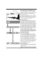
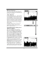
TVG (Time Variable Gain)
As the acoustic signal travels through the water it is
attenuated in strength and also loses strength because the
signal is being spread over a larger and larger area. For
this reason, distant targets appear weaker than close
targets - even if both targets of identical size.
The
Outlook’s receiver circuit includes a Time Variable
Gain (TVG) feature where the receiver’s gain is
controlled by the microprocessor and increases in value as
the depth or forward range increases. This feature tends
to compensate for the weakening of the signal at large
distances as the receiver’s gain will be increased as the
signal gets smaller. It is also helpful in minimizing
sidelobe problems as shown in the diagram at right.
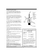
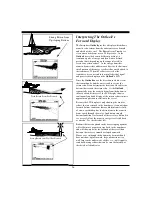
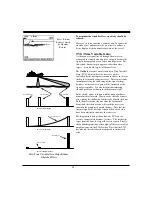
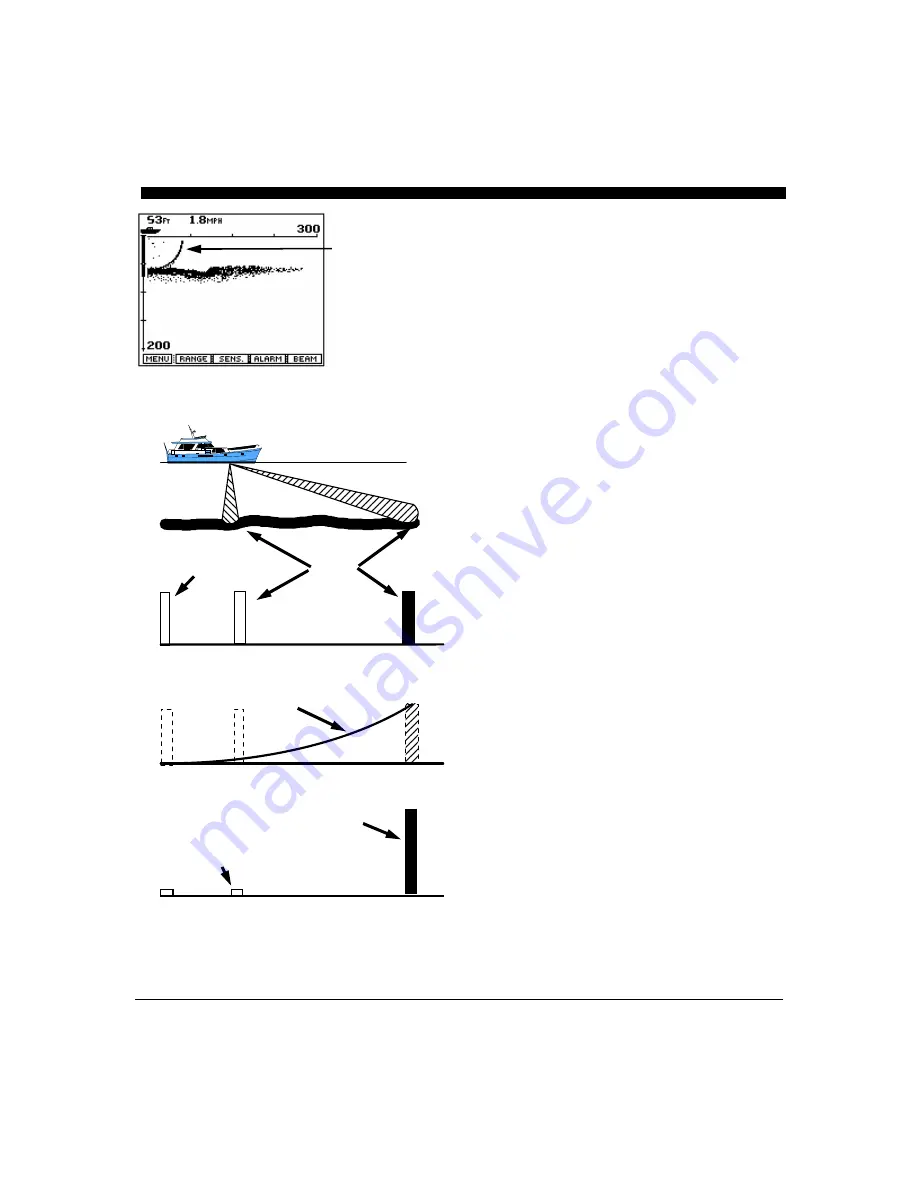
In the sketch, a boat is shown with the main transducer
beam aimed far forward. However, the sidelobe beam is
also striking the shallow bottom directly beneath the boat.
Both the desired echo (the one from the far forward
beam) and the sidelobe echo will reach the receiver as
shown in the graph just beneath the boat. Note that the
transmit signal, the sidelobe echo and the desired echo
have been arbitrarily shown as the same size.
The diagram just below shows how the TVG on the
receiver changes with distance (or time). The farther the
target from the boat, the larger the receiver gain. Finally,
the bottom diagram shows the output of the receiver after
amplification with the TVG feature. Note that the TVG
has reduced the sidelobe echo compared to the desired
echo.
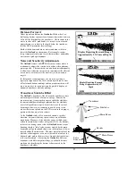
“False” Bottom
Echoes Caused
by Sidelobe
Returns.
Sidelobe Echo
Desired Echo
Transmit Pulse
Receiver Gain Level
Receiver Output Signals
Receiver Gain (TVG)
Receiver Input Signals
Sidelobe Echo
Desired Echo
How Time Variable Gain Helps Reduce
Sidelobe Effects
Summary of Contents for Outlook
Page 1: ...1 OPERATION MANUAL...
Page 36: ...36...


