


29
FREQUENTLY ASKED
QUESTIONS
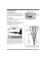
How wide is the scanning beam?
The phased array scanning beam on all
Interphase
scanning sonar operates with a 12 degree cone angle
beam. This means that the diameter of the beam at 100'
is about 15' wide. The transducer operates at
approximately 200 kHz. The beam has many unique
characteristics which allow increased resolution as well
as increased ranges.
How powerful (watts) are the Phased Array Sonar
units from Interphase?
Phased Array Sonar does not operate in the same way
that traditional marine sounders work.
Interphase
has
combined high-tech software with ultrasound technology
from the medical field and newly released military
ultrasound technology.
Interphase's
ultrasound
technology is now pending patent approvals. It operates
on approximately 420 watts (RMS tested at the
transducer or 3,200 watts peak to peak) but is channeled
through eight (8) separate elements and the signal is
phased via our software.
IMPORTANT NOTE: All sonar sounders, if more than
200 watts RMS, have a limited use in shallow water (less
than 10' from transducer to bottom). In most cases, the
need to see forward occurs when traveling from deeper
to shallower depths. Forward scanning is possible but
limited when the water is less than 10' deep. Some
clutter on the screen will occur in shallow environments.
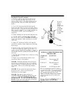
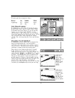
What type of transducer is needed and what does it
look like?
The transducers for both
Outlook
are available in
transom or thru-hull configurations. If you are operating
an inboard, you must use the thru-hull. Remember that
you are measuring ahead from the transducer, therefore,
placing it as far forward as possible will provide you
with greater forward range.
The thru-hull transducers are slightly smaller than a
tennis ball and extremely hydrodynamic (they pass
through water in a streamlined fashion).
The transom transducers are mounted on a stainless steel
kick-up bracket in order to minimize the possibility of
damage if striking a floating object. The transom bracket
will 'kick-up' at speeds in excess of 30 knots. Therefore,
if you intend on using the forward scan
at
high speed,
you will need to consider a thru-hull transducer.
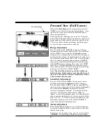
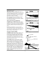
How far ahead will I be able to see?
In most cases, forward scanning with the
Outlook
is
approximately six (6) times farther ahead than the depth
of water. For example, if you are in 15' of water, you can
see about 90' ahead of the transducer. The range is
limited to 600' forward and 400' in depth.
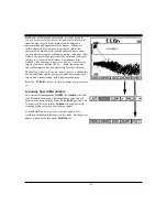
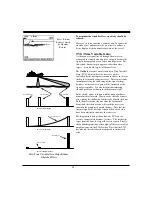
Typically, if you are attempting to see great distances
ahead, only targets but not the bottom will appear
beyond 300 feet ahead, because a flat bottom with no
targets (rocks, wrecks, fish, etc.) will be stealth or
invisible to sonar pulses at great distances. A rocky
bottom or approaching hazard will normally show up
clearly on the display, even far ahead.
Summary of Contents for Outlook
Page 1: ...1 OPERATION MANUAL...
Page 36: ...36...